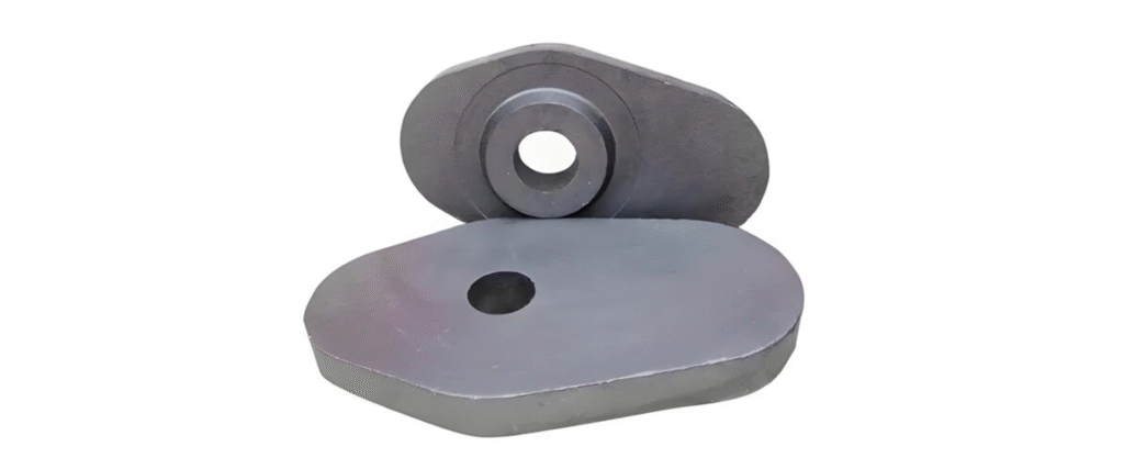
introduction of Isostatical refractory
Definition of the three isostatical refractory
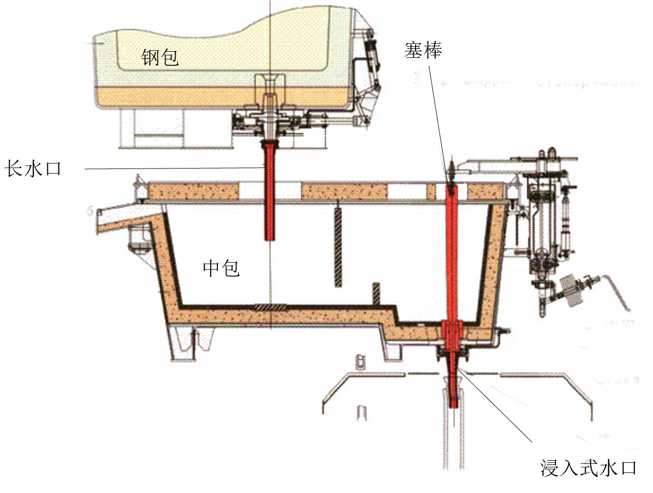
the monolithic stopper rod, the ladle shroud, and the submerged entry nozzle—are essential refractory materials used in continuous steel casting. They primarily serve to protect the casting process (ladle shroud and submerged entry nozzle) and control the flow of molten steel (stopper rod).
Here is the table that explain the function of ladle shroud,tundish stopper,sub entry shroud,and ladle shroud manipulator
| Component | Primary Function |
|---|---|
| Submerged Nozzle | Controls molten steel flow to prevent contamination and maintain consistent temperature. |
| Tundish Shroud | Manages the flow between ladle and tundish, ensuring a steady steel supply while reducing splashes and air exposure. |
| Tundish Stopper | Regulates molten steel flow rate, providing control during the continuous casting process. |
| Ladle Shroud | Protects molten steel from oxidation during transfer from ladle to tundish, improving steel purity. |
| Ladle Shroud Manipulator | Allows for accurate and safe placement of ladle shrouds, ensuring optimal molten steel transfer and increasing operator safety in the continuous casting process. |
Classification of stoppers:
- Based on additional functions, they can be classified as:
a: Standard stopper
b: Ventilated stopper

2. Classification by connection method:
a: Threaded type
b: Pin-type

Classification of submerged tundish nozzles
- Submerged tundish nozzles for square and round billets
- Submerged tundish nozzles for medium-thick slabs
- Submerged tundish nozzles for thin slabs
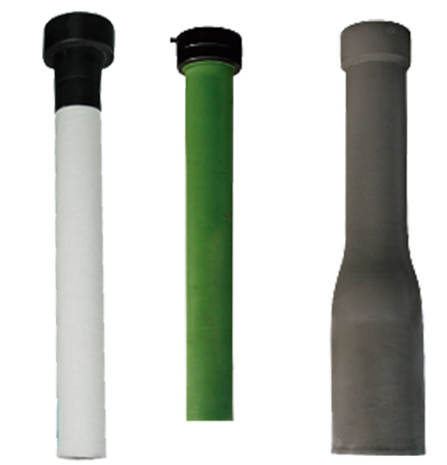
Types of ladle shroud:
- Standard ladle shroud
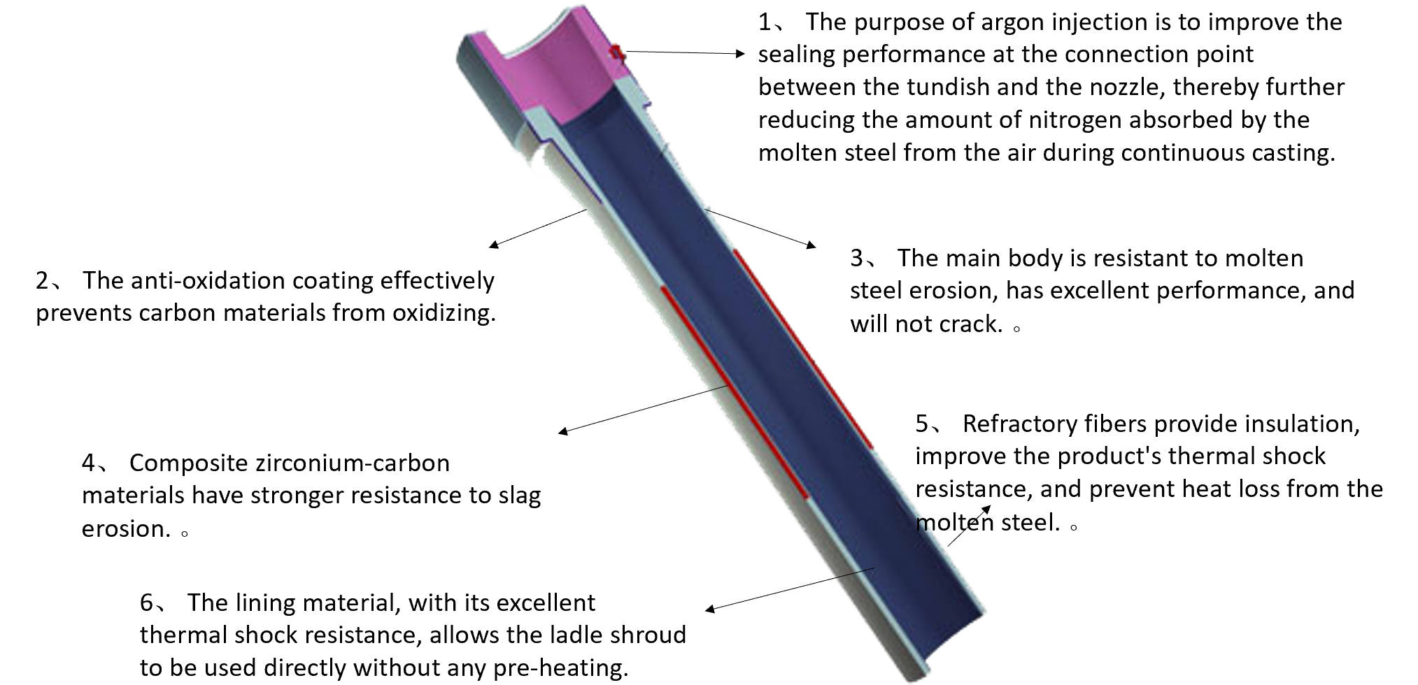
- Argon-shielded ladle shroud
the design and production of isostatical refractory
Stopper Rod Body Design:
The rod body design takes into account safety and installation factors. The overall wall thickness of the rod must be greater than 40mm, and at the slag line, it must be no less than 50mm. If a carbon fiber plug is used, the wall thickness at the plug location must be no less than 30mm.
The design of sections A and B of the rod tail: The rod tail consists of two sections. Section A is a straight section, which ensures high strength near the plug. Section B is a tapered section, which ensures the required slag line thickness.
Additionally, the inner core diameter must be controlled. Increasing the inner core diameter can reduce rod bending and core deformation, but it also reduces the rod wall thickness.
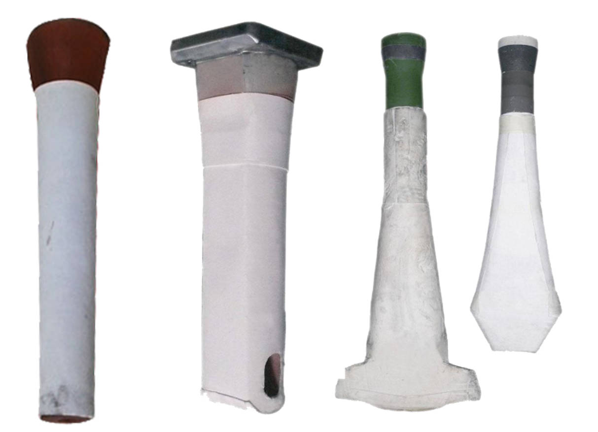
Stopper Head Design:
Common types of stopper head include:
1. Semi-circular tip;
2. Three-segment arc tip;
3. Two-segment arc tip;
4. Two-arc with diagonal line tip.
The taper of these four types of plug tips gradually decreases from left to right. A larger taper results in longer lifespan and stronger wear resistance, but poorer flow control accuracy. This type of head is suitable for slab casting with high flow rates and severe wear. Conversely, a smaller taper results in shorter lifespan and weaker wear resistance, but better flow control accuracy. This type of plug is suitable for billet casting with lower flow rates and less slag carryover. Currently, the most commonly used plug tip is the three-segment arc type. This type offers good wear resistance and high flow control accuracy, and its taper can be adjusted by varying the radius of the three arcs to suit most continuous casting applications.
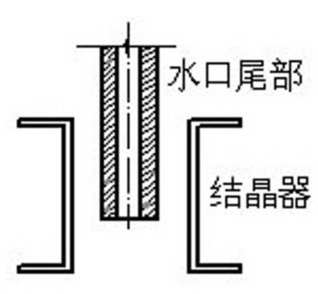
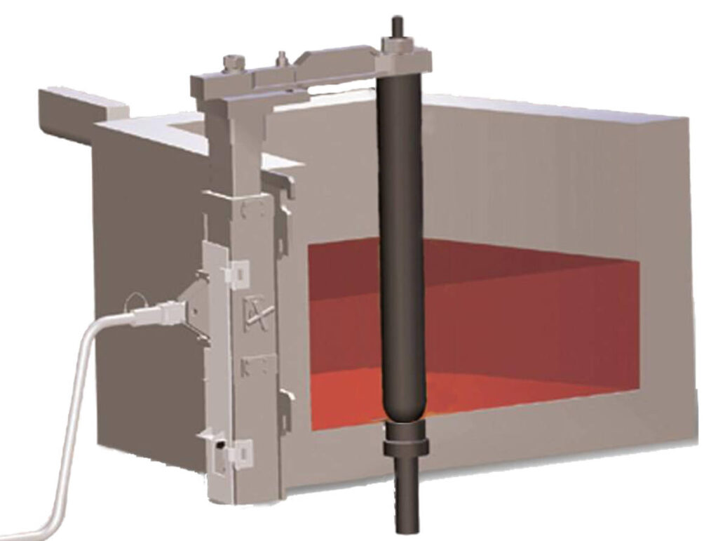
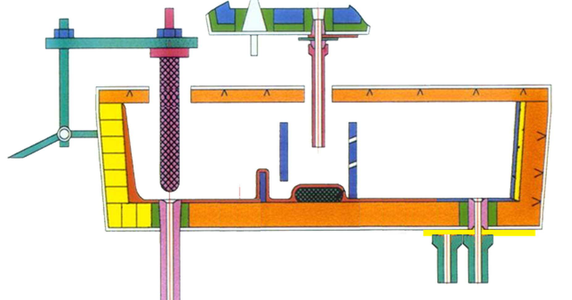
Relationship between the stopper rod and the tundish nozzle
The effective stroke of the stopper rod is related to the shape and dimensions of the stopper rod and the tundish nozzle as follows:
Where:
Y…Effective stroke of the stopper rod;
Rn…Radius of the tundish nozzle;
x…Contact angle between the stoper rod and the tundish nozzle;
y…Radius of the contact circumference between the stopper rod and the tundish nozzle.
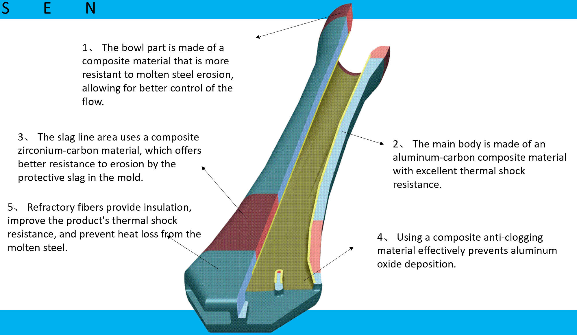
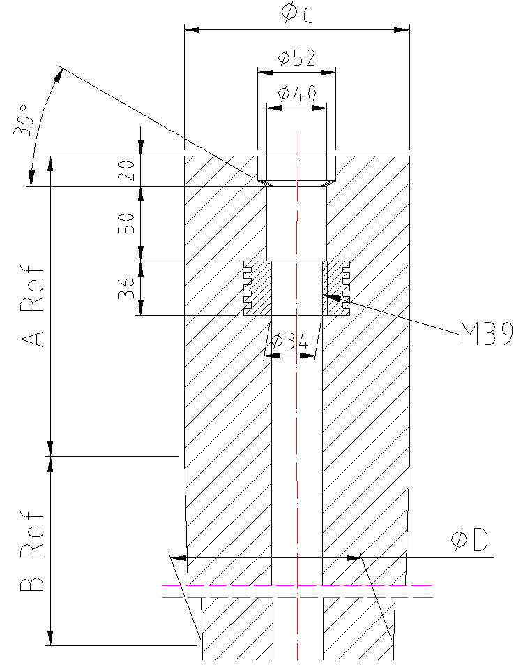
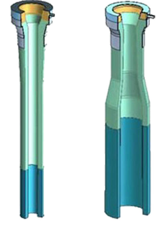
Sub Entry Nozzle Design
Figure A shows a conical design, while Figure B shows a combination of a cylindrical and conical shape.
In the figures:
φA – Outer diameter of the top surface of the conical or cylindrical sprue;
φB – Opening diameter of the sprue bowl;
φC – Diameter at the point where the arc of the sprue bowl is tangent to the flow channel of the molten metal; this line is called the throat line;
φD – Outer diameter of the bottom end of the conical sprue;
R – Radius of the arc of the sprue bowl;
h – Height of the conical section;
h1 – Depth of the throat line;
h2 – Height of the cylindrical section of the sprue bowl;
h – Total height of the cylindrical and conical sections of the sprue.
SEN Rear design:
Side-entry hole design and slag line design
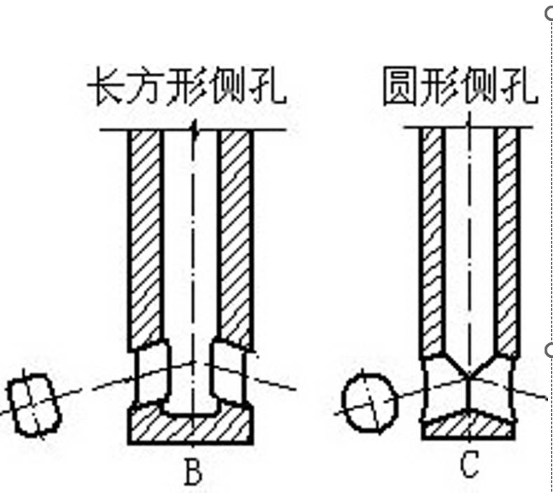
Empirical Dimensions for Side-Port Steel Pouring:
The total cross-sectional area of the two side ports should be slightly larger than or equal to twice the cross-sectional area of the central pouring channel. This ensures a stable steel flow and slow expansion rate.
Side Port Inclination Angle:
The inclination angle of the side ports can be horizontal, upward, or downward, typically ranging from 15° to 30°. Currently, a 15° downward inclination is more common. The thickness of the bottom of the side port is generally controlled between 25 and 40 mm.
Slag Line:
Due to the vibration frequency and amplitude of the mold, this area is subjected to alternating erosion by the protective slag and molten steel, forming a crescent-shaped groove with a width of 50–60 mm. The thickness (b) of the slag line layer is generally between 8 and 15 mm, and its height (h) is calculated as follows: Slag line height h = 3 × (50–60 mm)
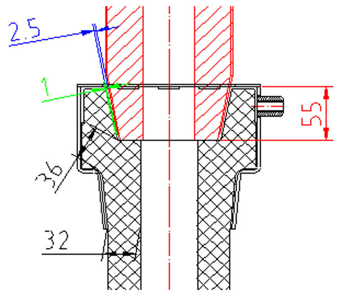
Ladle shroud Bowl rim design
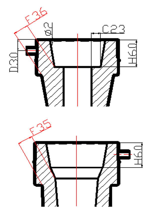
Classification of bowl lip designs:
- Step-type lip: Advantages: Compared to a conical lip, it reduces pressure on the lip and facilitates removal of the slag.
- Conical lip.
Dimensioning:
For a step-type lip, the dimension C (step height) should be determined based on the thickness of the ladle nozzle wall, ensuring that the inner diameter of the nozzle is greater than the mating depth H (generally 45–70 mm). The sealing area between the nozzle and the lip is located on the step, and the taper angle of the inclined edge should be determined based on the taper angle of the ladle nozzle.
Designed to work in conjunction with the lower nozzle.
Ladle shroud dimention design
- The distance between the bottom of the ladle and the liquid level in the tundish;
- Whether the ladle can be lifted, and whether changing the tundish nozzle is convenient;
- Ensure that the bottom of the tundish nozzle is at least 350mm above the bottom of the tundish, with the immersion depth in the liquid level being between 150 and 300mm.
Diameter and Thickness Design:
The diameter is designed based on the molten steel flow rate and the shape of the tundish nozzle. The minimum inner diameter of the tundish nozzle should be at least 10mm larger than the minimum diameter of the ladle outlet to ensure smooth flow of molten steel and prevent spillage. The wall thickness of the tundish nozzle is generally between 25 and 35mm.
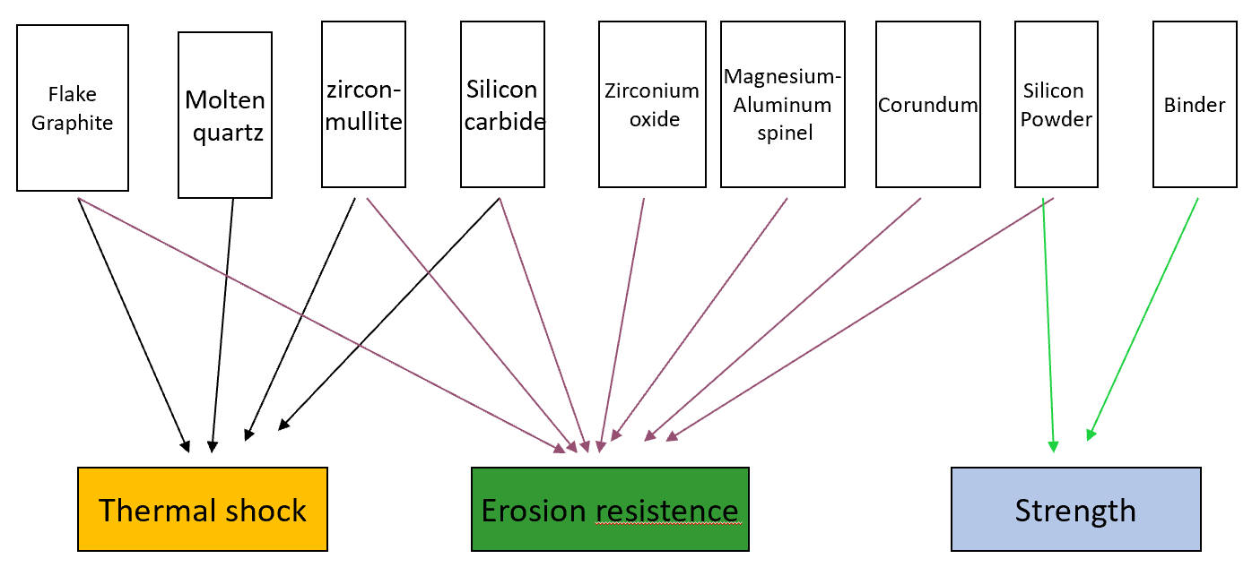
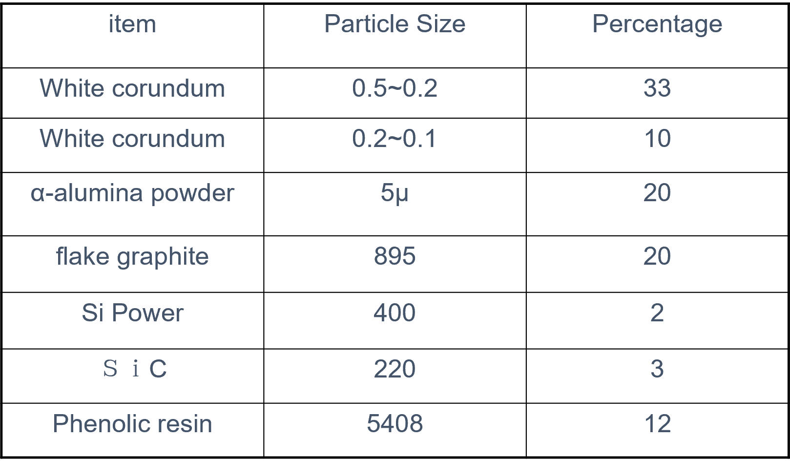
The design concept for raw materials
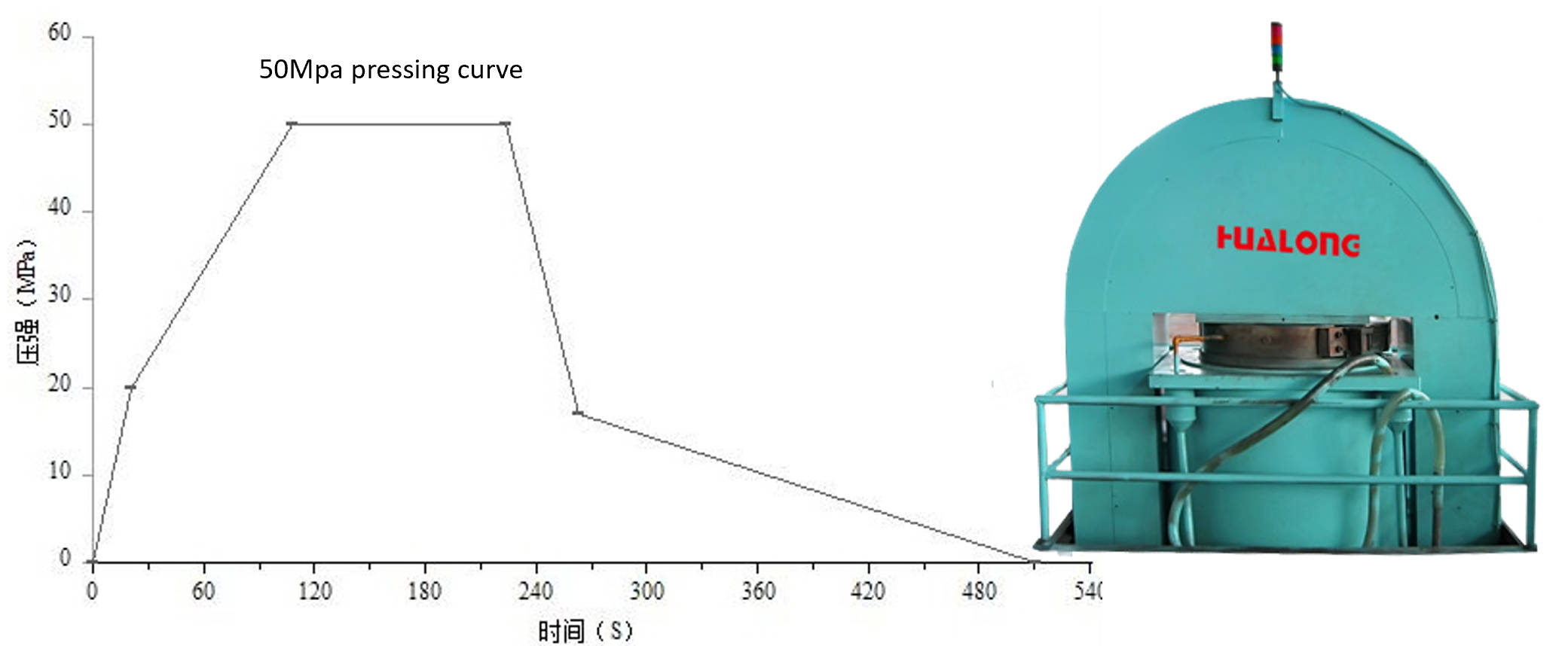
Production process
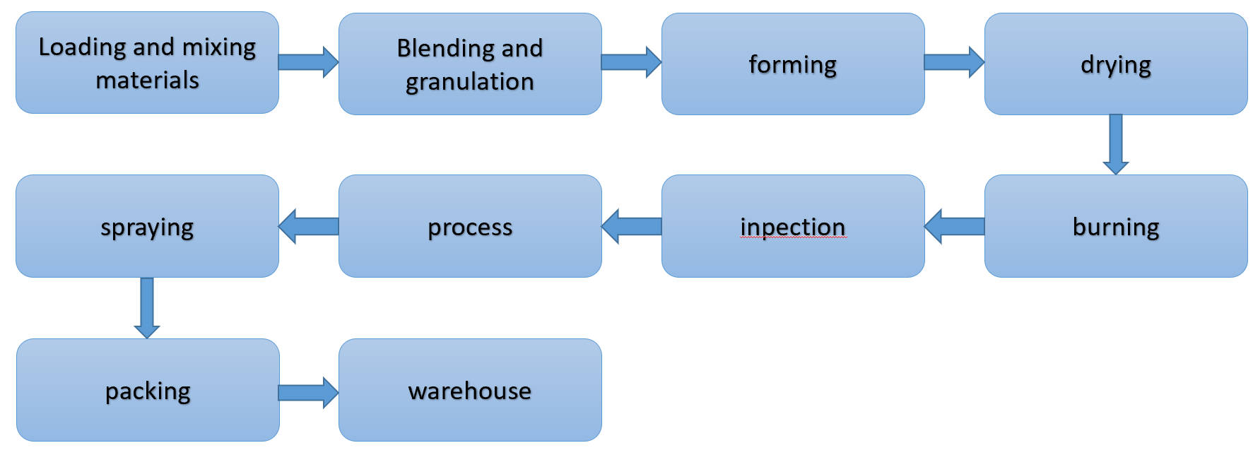
mixing
particling
ØFor dry-pressing of ceramic materials, the powder must have good flowability, high bulk density, and minimal or no fine particles; furthermore, the amount of binder used must be precisely controlled.
ØThere are currently three commonly used methods for granulating dry powder feedstock: conventional granulation, pressure granulation, and spray granulation.
ØIn production, it is generally necessary to control the particle size, moisture content, and plasticity of the granules.
forming
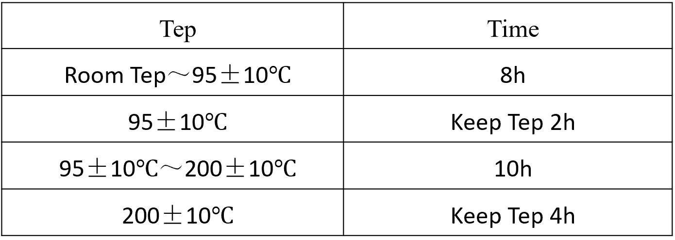
Drying
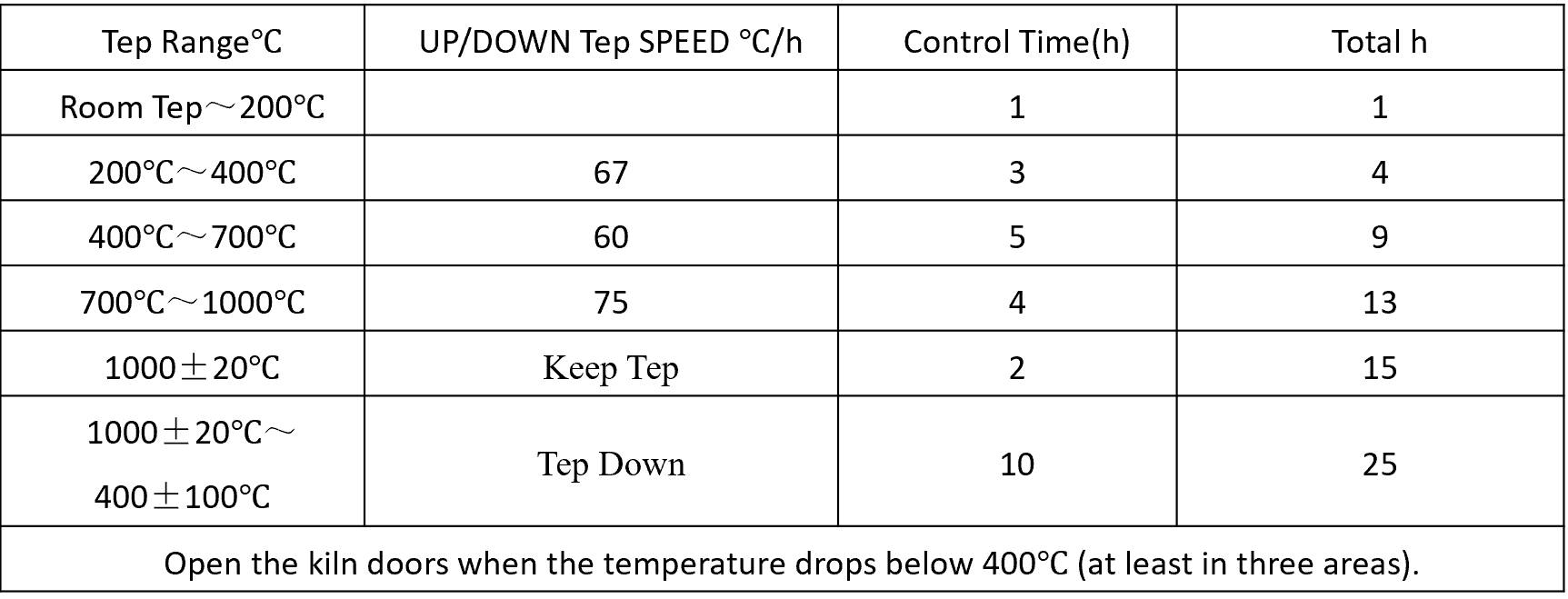
Burning
Inspection-process-spraying
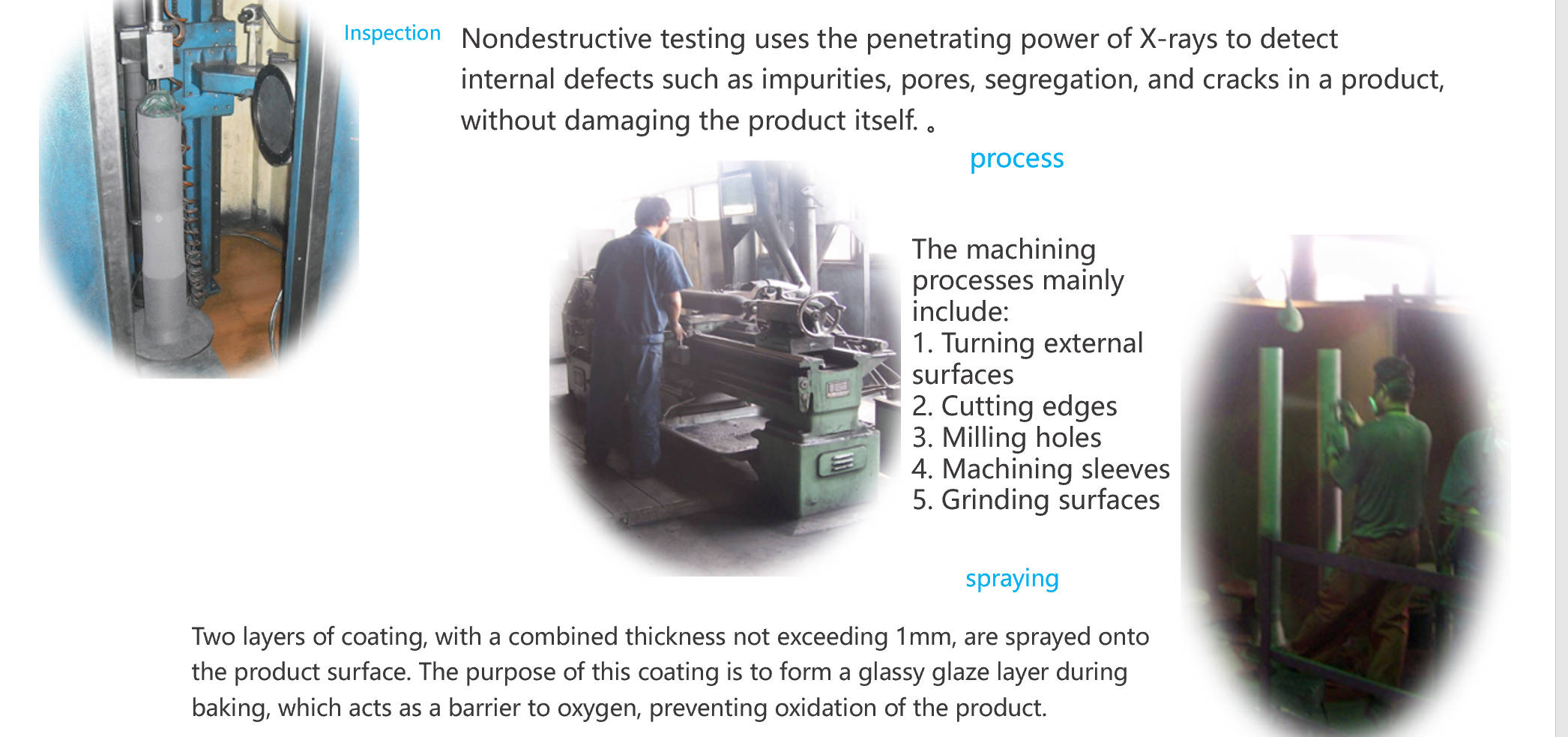
1.Nondestructive testing uses the penetrating power of X-rays to detect internal defects such as impurities, pores, segregation, and cracks in a product, without damaging the product itself.
2.The machining processes mainly include:
- Turning external surfaces
- Cutting edges
- Milling holes
- Machining sleeves
- Grinding surfaces
3.Two layers of coating, with a combined thickness not exceeding 1mm, are sprayed onto the product surface. The purpose of this coating is to form a glassy glaze layer during baking, which acts as a barrier to oxygen, preventing oxidation of the product.
the installation and application of isostatical refractory
Stopper installation
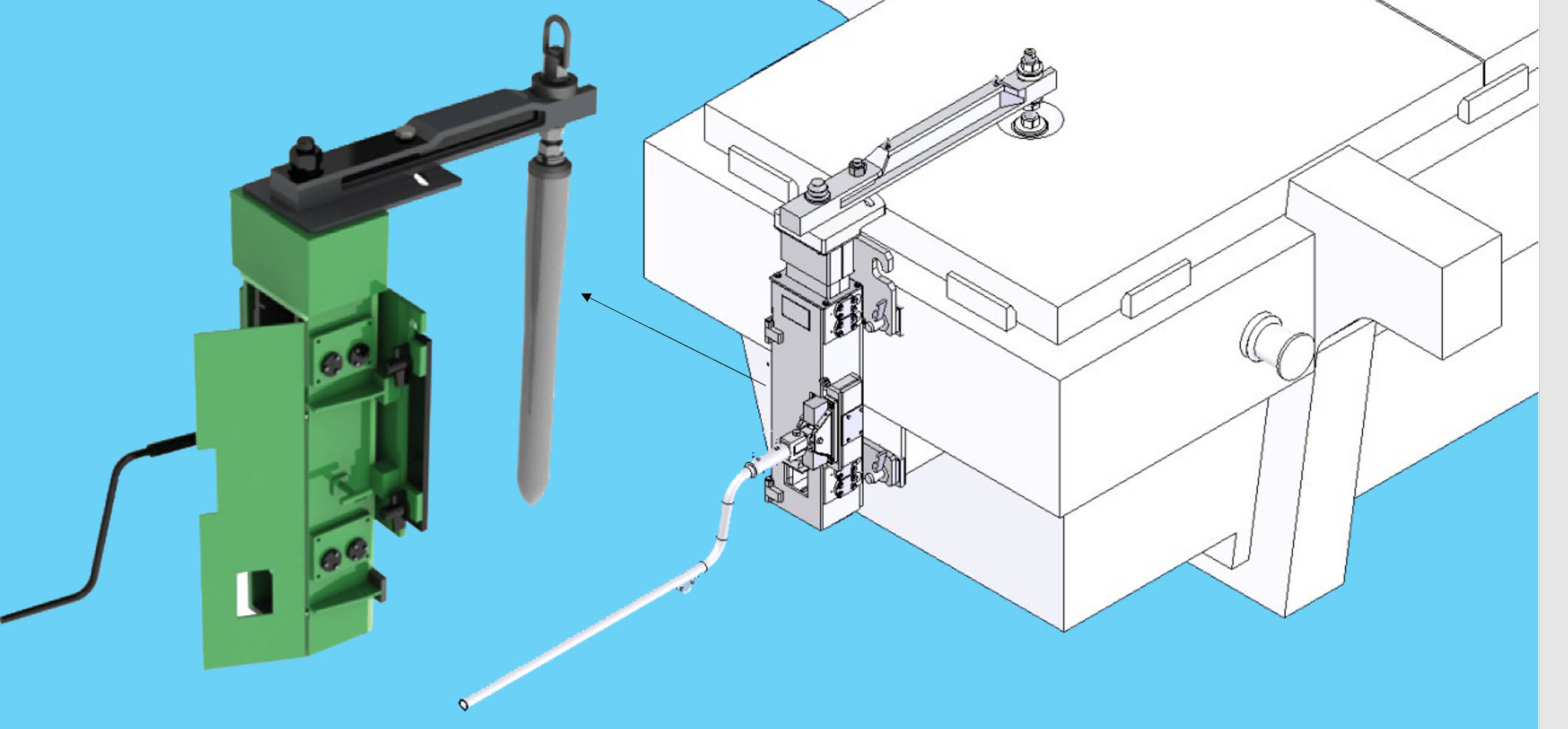
Installation process
Notes
1、 The mechanism should be designed to ensure good performance; it should be thoroughly tested and adjusted to guarantee sufficient lubrication.
2、 During installation, pay attention to ensuring proper alignment with the tundish nozzle position. ;
3、 Prevent any debris from accumulating between the stopper rod and the tundish nozle, as this could cause molten steel to leak out and result in a failed casting process.
4、 Be careful to protect the plug pin; do not hit it directly. When adjusting the switch, use appropriate force; avoid damaging the protective coating on the surface.
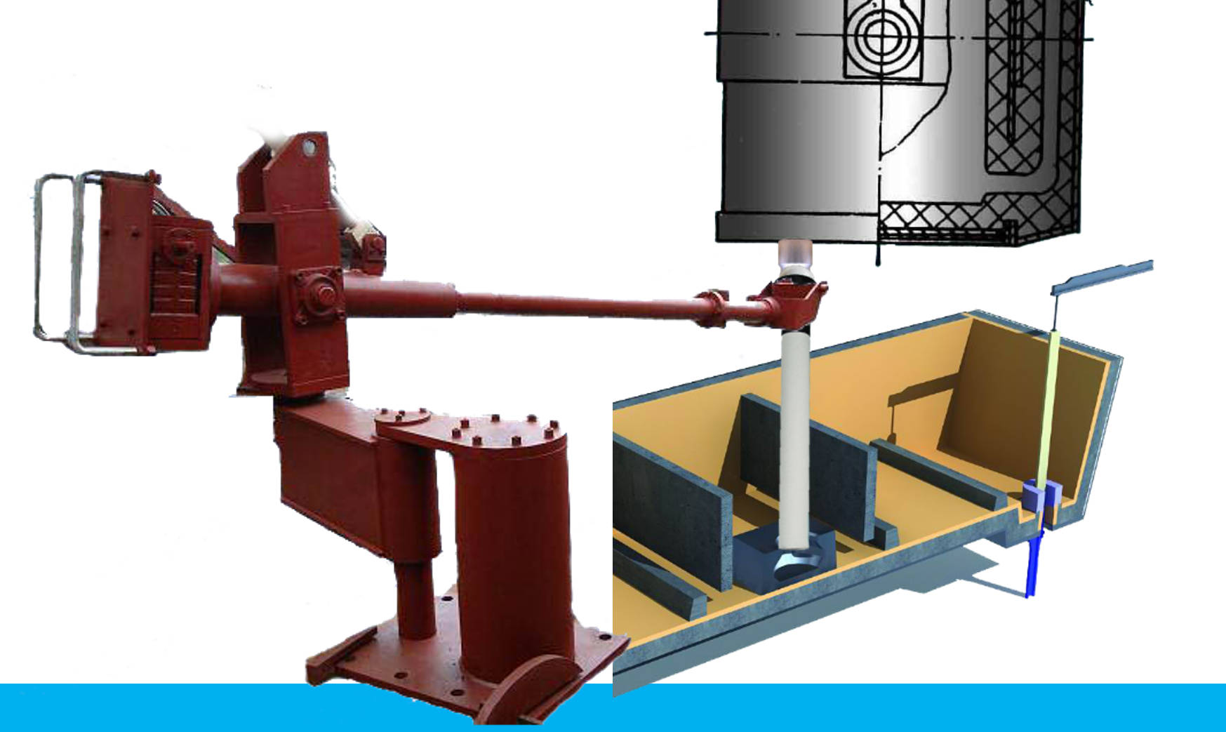
Sub entry nozzle installation
the common problem of isostatical refractory
broken rod
1、 Fractures during installation or baking are mainly caused by impacts that occur during the installation and adjustment process. 。
2、 The stopper rod fractured at the slag line, primarily due to the poor wear resistance of the material at that point; therefore, the material composition of the slag line area of the stopper rod should be adjusted.
3、 Some steel mills intentionally offset the center line of the stopper rod by 5-10mm from the center line of the tundish nozzle during installation, to improve the operator’s control during operation. However, this can easily cause the rod tip to collide with the nozzle opening during operation, resulting in the stopper rod breaking.
4、 It is also important to be vigilant against sabotage by competitors on site, such as pouring water into the hole of the sealing rod.
Stopper Head drop
tundish stopper head adhesion
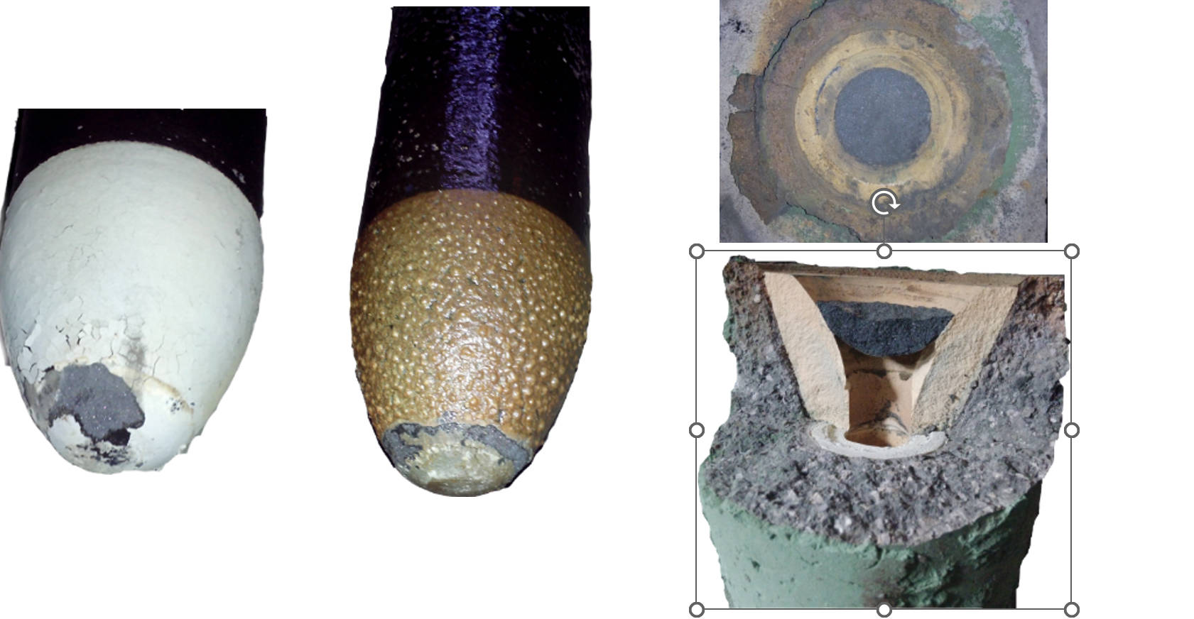
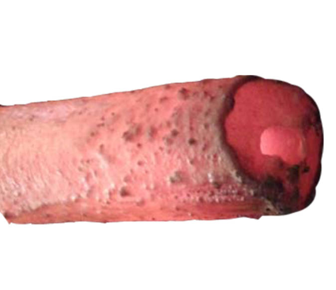
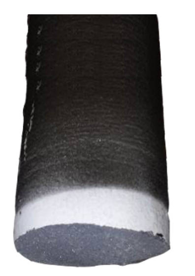
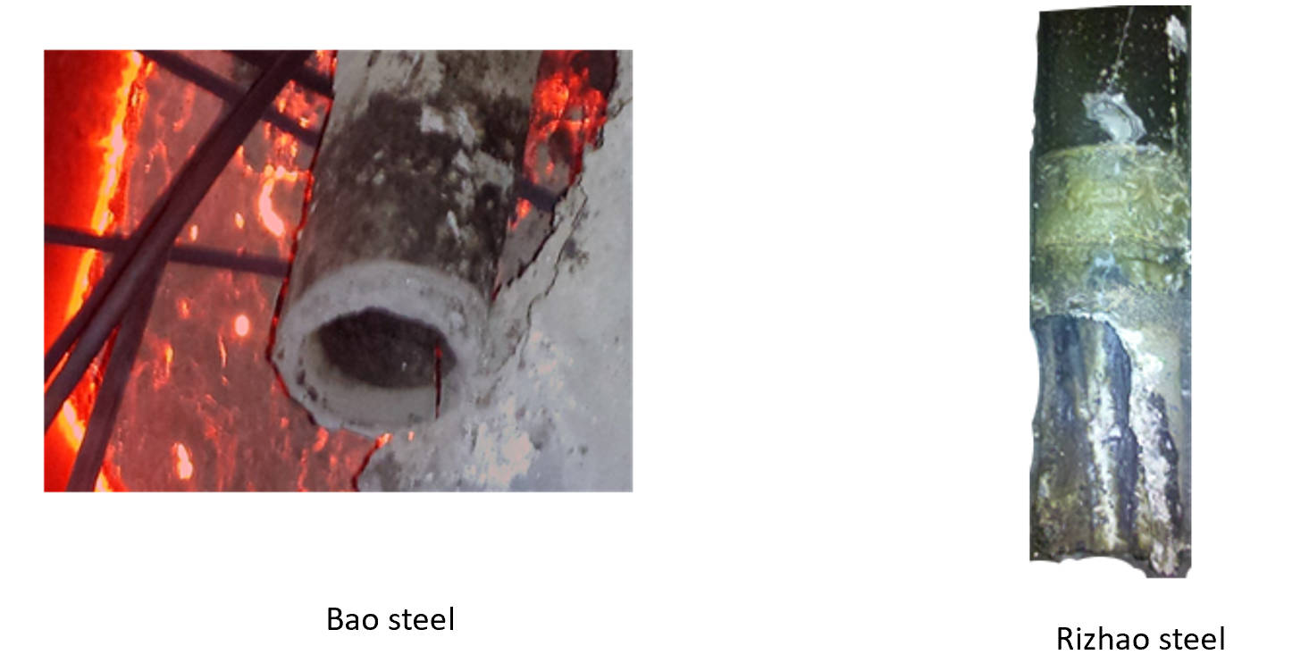
Stopper Rod head erosion
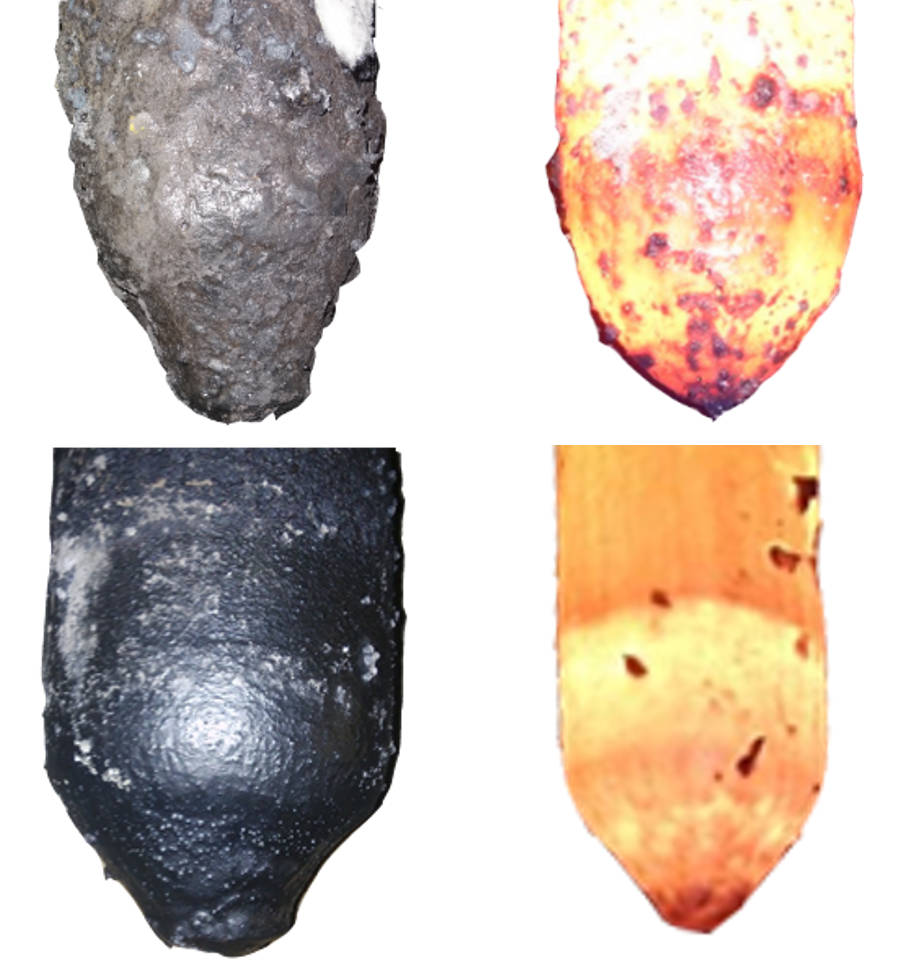
1.shape
2.special steel
3.agroning
4.Oxygen content (after combustion)
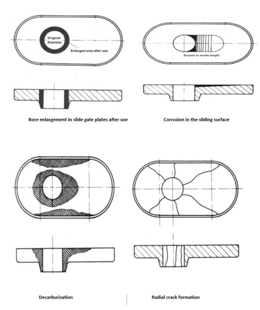
Ladle shroud problem
- Thermal shock damage
- Slab erosion
- Internal hole enlargement
- Cracking and perforation
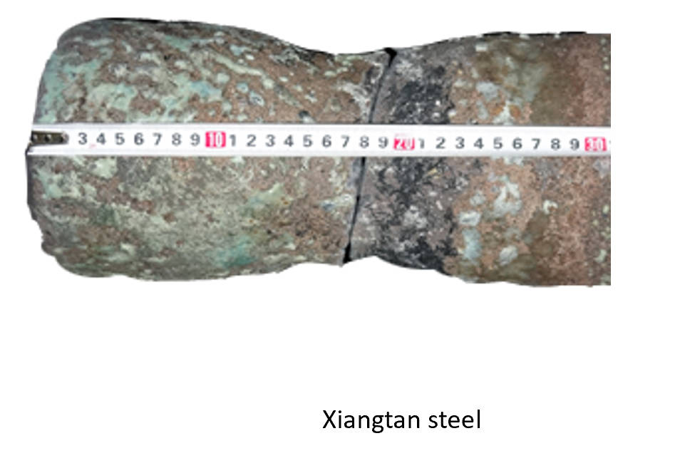
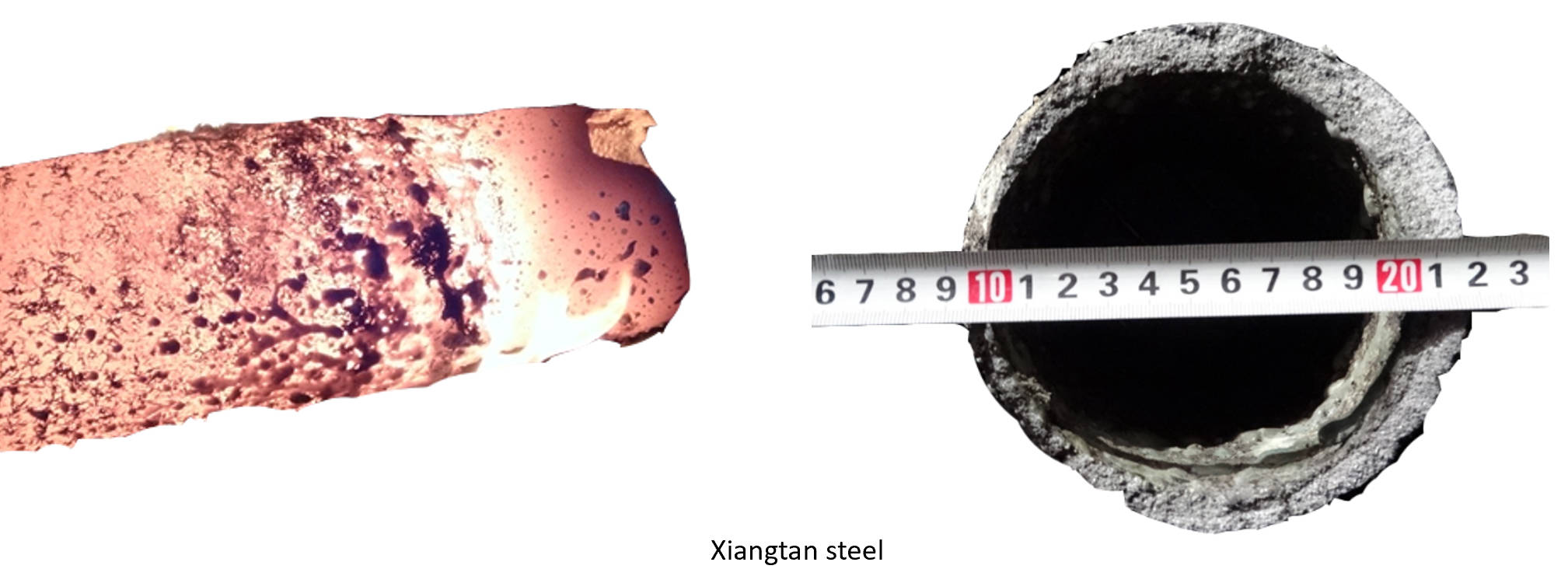
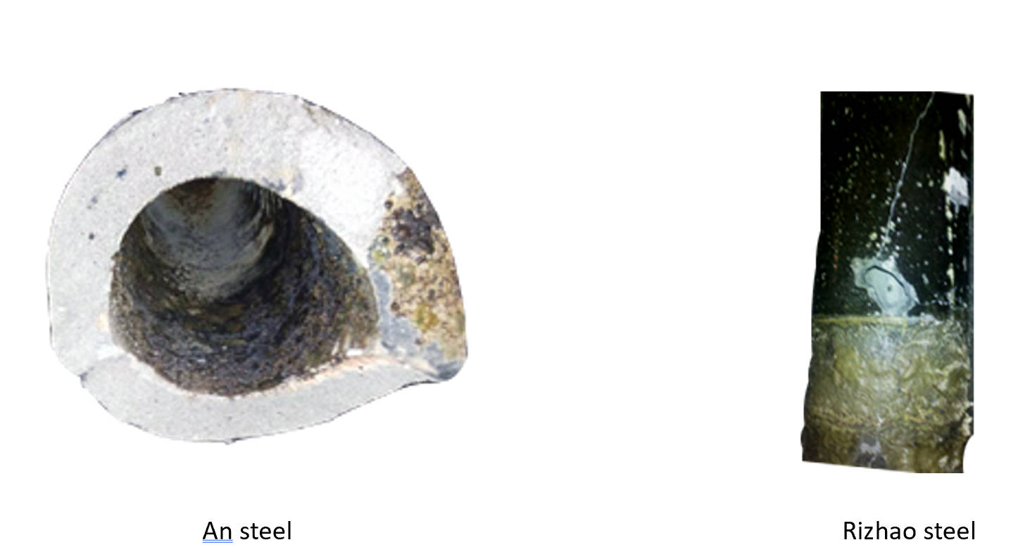
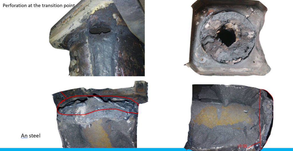
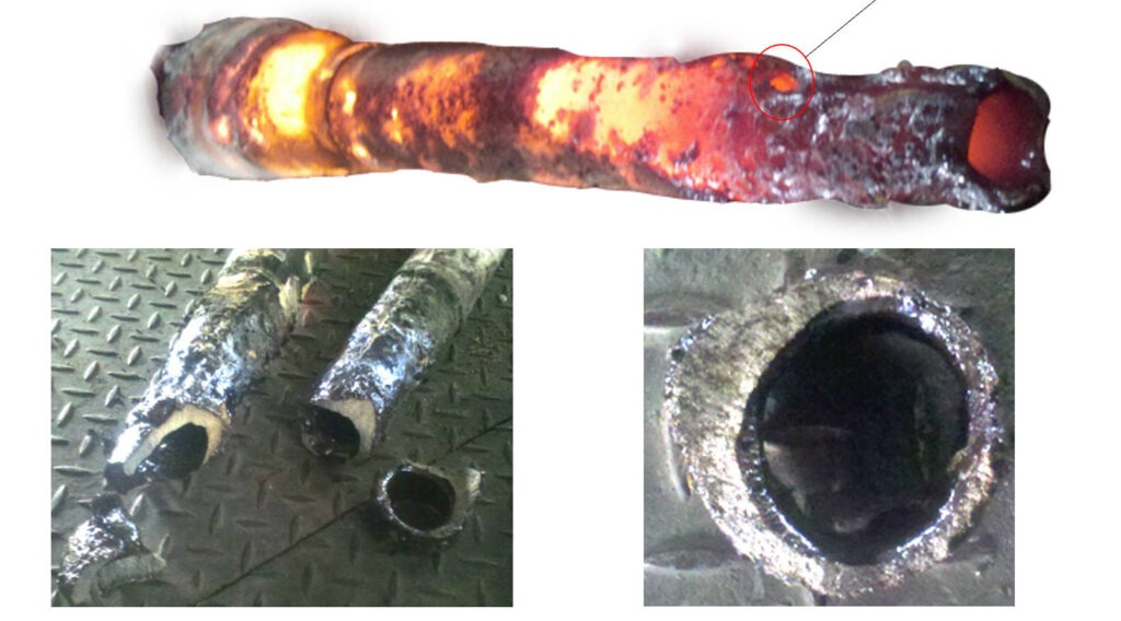
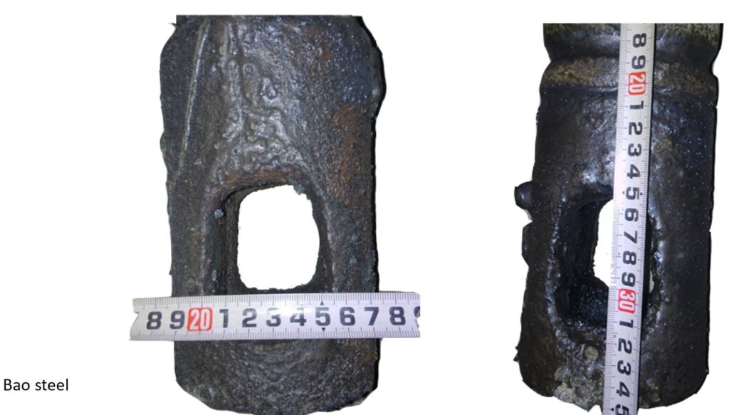
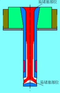
Sub Entry Nozzle problem
- Perforation at the transition point
- Perforation due to slag erosion
- Enlargement of internal and side holes
- Formation of clogging inside the mold cavity; blockage of the pouring gate