1. Introduction
The ladle shroud is a critical refractory component in continuous casting operations, serving as the protected conduit that transfers molten steel from the ladle nozzle to the tundish. Its primary function is to prevent reoxidation, minimize air aspiration, and ensure a stable, clean steel stream. Despite its relatively simple tubular geometry, the ladle shroud operates under extremely aggressive conditions, including high-temperature exposure (>1600°C), turbulent steel flow, slag interaction, thermal cycling, and mechanical loading.
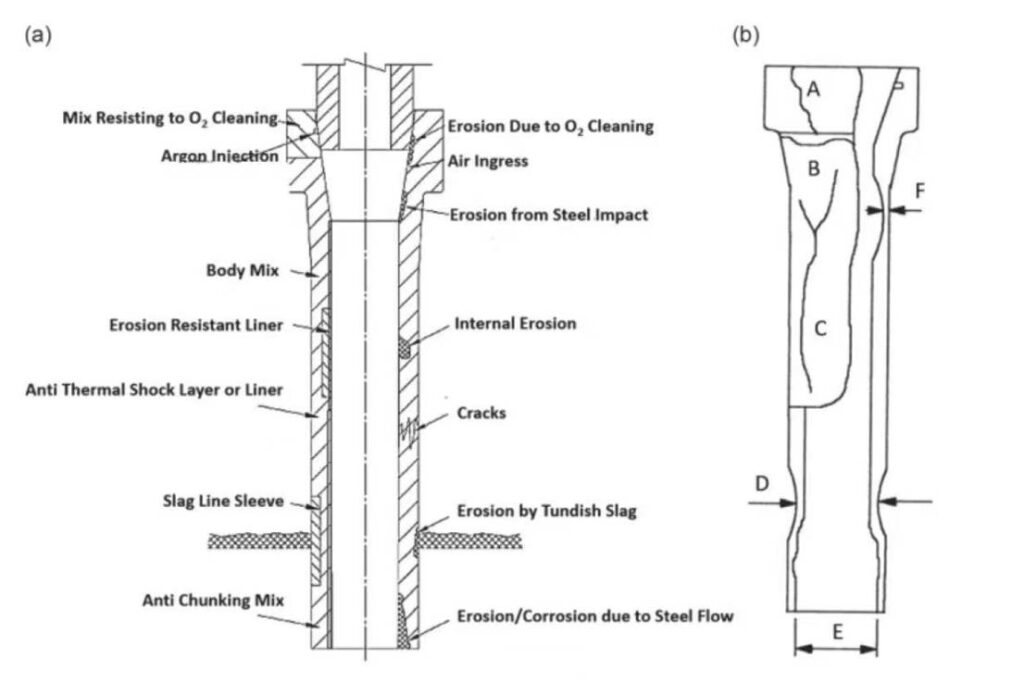
Failure of the ladle shroud can result in severe consequences, such as steel contamination, casting interruptions, nozzle clogging, or even safety hazards. Based on the schematic and classification shown in the provided image, the failure of the ladle shroud can be attributed to a combination of mechanical, thermal, chemical, and operational factors, categorized from A1 to F1.
This article provides a detailed technical analysis of these probable failure causes, their mechanisms, and practical mitigation strategies.
2. Critical Failure Zones in Ladle Shroud
Before analyzing individual causes, it is essential to understand the typical failure zones in a ladle shroud:
- Upper connection zone (near ladle nozzle)
- Mid-body region (subjected to internal erosion and thermal gradients)
- Slag line region (interface with tundish slag layer)
- Bottom outlet region (high-velocity flow and impact zone)
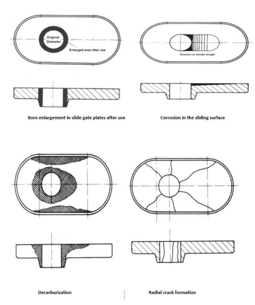
Failures typically manifest as:
- Cracks and spalling
- Internal bore enlargement
- Localized corrosion
- Structural distortion or bending
- Catastrophic breakage
3. Mechanical Failure Factors (A-Series and B-Series)
3.1 A1 – Excessive Counterweight Force
In many ladle shroud systems, a counterweight mechanism is used to stabilize and position the shroud. However, excessive counterweight force can introduce:
- Compressive stress at the upper interface
- Bending moments along the shroud body
- Localized stress concentration at the holding ring
This can lead to:
- Crack initiation near the top section
- Progressive deformation
- Reduced structural integrity
Mitigation:
- Optimize counterweight calibration
- Ensure load distribution is uniform
- Use mechanical supports with controlled flexibility
3.2 A2 – Ladle Nozzle Mismatch
Mismatch between the ladle nozzle and the shroud inlet is a critical installation issue. It results in:
- Non-uniform contact pressure
- Air ingress due to poor sealing
- Localized turbulence at the entry point
Consequences include:
- Accelerated erosion due to impinging steel flow
- Oxidation from air suction
- Thermal stress concentration
Mitigation:
- Ensure dimensional compatibility
- Use proper gasket or sealing materials
- Perform alignment checks before casting
3.3 B1 – Poor Condition of Holding Ring
The holding ring secures the shroud to the ladle nozzle. If it is worn, corroded, or deformed:
- Clamping becomes uneven
- Shroud alignment is compromised
- Vibrations increase during casting
This leads to:
- Mechanical fatigue
- Crack propagation
- Increased risk of detachment
Mitigation:
- Regular inspection and replacement
- Use high-strength, heat-resistant alloys
- Maintain proper clamping force
3.4 B2 – Insufficient Clearance Between Nozzle and Ring
Insufficient clearance creates excessive mechanical constraint:
- Thermal expansion cannot be accommodated
- Compressive stress builds up during heating
- Microcracks develop due to restricted movement
Mitigation:
- Maintain design clearance tolerances
- Consider thermal expansion coefficients during design
- Avoid overly tight assembly
4. Material and Thermal Factors (C-Series)
4.1 C1 – Insufficient Oxidized Protective Layer
A controlled oxidized layer on carbon-containing refractories acts as a protective barrier. If this layer is insufficient:
- Carbon oxidation accelerates
- Structural cohesion decreases
- Surface becomes more reactive to slag
This results in:
- Rapid degradation of the shroud wall
- Increased porosity
- Reduced erosion resistance
Mitigation:
- Optimize preheating procedures
- Use anti-oxidation additives (e.g., SiC, Al)
- Ensure proper storage to prevent premature oxidation
4.2 C2 – Excessive Moisture Pickup
Moisture absorption is a serious issue for refractory components. Excess moisture leads to:
- Steam generation during heating
- Internal pressure buildup
- Explosive spalling
Consequences include:
- Immediate structural damage
- Crack formation
- Reduced service life
Mitigation:
- Store shrouds in dry conditions
- Preheat adequately before use
- Avoid exposure to humid environments
5. Chemical and Metallurgical Factors (D-Series and E-Series)
5.1 D1 – Aggressive Tundish Cover Powder
Tundish cover powders are designed to insulate and protect molten steel, but aggressive compositions (high FeO, alkalis, fluorides) can:
- Chemically attack the shroud outer surface
- Penetrate through pores
- React with alumina or carbon phases
This leads to:
- Corrosion thinning
- Surface softening
- Accelerated wear at slag line
Mitigation:
- Optimize powder chemistry
- Use compatible refractory compositions
- Monitor slag aggressiveness
5.2 D2 – Slag Carryover
Slag carryover from the ladle introduces reactive phases into the tundish:
- FeO-rich slag increases oxidation potential
- Promotes chemical erosion
- Enhances inclusion formation
Effects include:
- Localized corrosion at slag interface
- Flow instability
- Reduced steel cleanliness
Mitigation:
- Improve slag detection and control
- Use slag-stopping devices
- Optimize ladle metallurgy practices
5.3 E1 – Slag/Powder Entrapment
Entrapment of slag or powder between the shroud and steel stream causes:
- Flow disturbance
- Localized thermal gradients
- Chemical reactions at the interface
This results in:
- Irregular erosion patterns
- Internal blockage
- Increased turbulence
Mitigation:
- Maintain steady casting conditions
- Control powder feeding
- Ensure proper shroud immersion depth
6. Operational Factor (F-Series)
6.1 F1 – Shroud Not Vertically Positioned
Proper alignment of the ladle shroud is essential. If the shroud is not vertical:
- Steel flow becomes asymmetric
- One side experiences higher erosion
- Bending stress develops along the body
Consequences:
- Uneven wall thinning
- Crack formation
- Risk of catastrophic failure
Mitigation:
- Use alignment tools during installation
- Monitor positioning during operation
- Train operators for proper setup
7. Combined Failure Mechanisms
In practice, ladle shroud failure rarely results from a single factor. Instead, multiple mechanisms interact:
- Mechanical + thermal stress → crack initiation
- Cracks + slag penetration → accelerated corrosion
- Corrosion + flow erosion → wall thinning and rupture
For example:
- A misaligned shroud (F1) combined with aggressive slag (D1) leads to rapid asymmetric wear.
- Excessive counterweight (A1) combined with poor oxidation protection (C1) results in structural collapse.
Understanding these interactions is essential for effective failure prevention.
8. Preventive Strategies and Best Practices
To minimize ladle shroud failure, steel plants should implement:
Design Optimization
- Use high-quality alumina-carbon or zirconia-based materials
- Incorporate anti-oxidation additives
- Design for thermal expansion compatibility
Operational Control
- Maintain stable casting speed
- Ensure proper shroud alignment
- Avoid sudden thermal shocks
Material Handling
- Store in dry, controlled environments
- Preheat before use
- Avoid mechanical damage during handling
Process Control
- Minimize slag carryover
- Optimize tundish powder chemistry
- Monitor steel cleanliness
Maintenance
- Inspect holding rings and mounting systems
- Replace worn components
- Calibrate counterweight systems
9. Conclusion
The ladle shroud is a vital component in continuous casting, directly influencing steel quality, process stability, and operational safety. Its failure is a complex, multi-factor phenomenon involving mechanical stress, thermal gradients, chemical attack, and operational misalignment.
By systematically analyzing the failure causes—from A1 excessive counterweight force to F1 improper vertical positioning—engineers can identify root causes and implement targeted improvements. Through optimized design, controlled operation, and disciplined maintenance practices, the service life of ladle shrouds can be significantly extended, ensuring safer and more efficient steel production.