the ladle’s trunnions in a horizontal position—as the standard reference, the layout can be categorized into “top-opening,” “bottom-opening,” and “side-opening” configurations, depending on the position of the hydraulic cylinder.
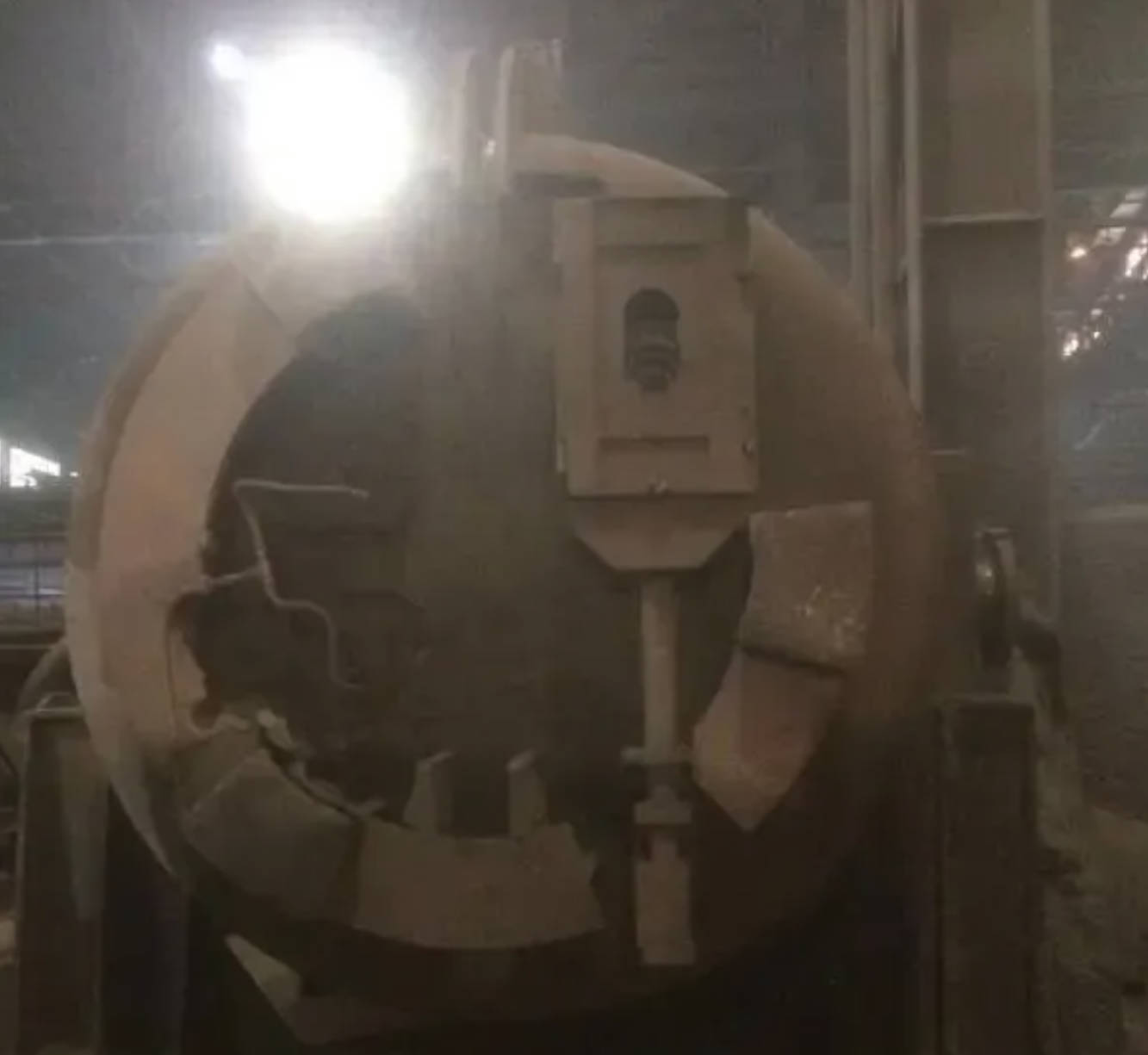
Top-opening configuration
As shown in Figure 3-1
In this arrangement, the hydraulic cylinder is located above the mechanism. Cylinder insertion and removal are convenient, and the structural layout is simple.
Disadvantage: the hydraulic cylinder is easily exposed to radiant heat from molten steel during opening and pouring.
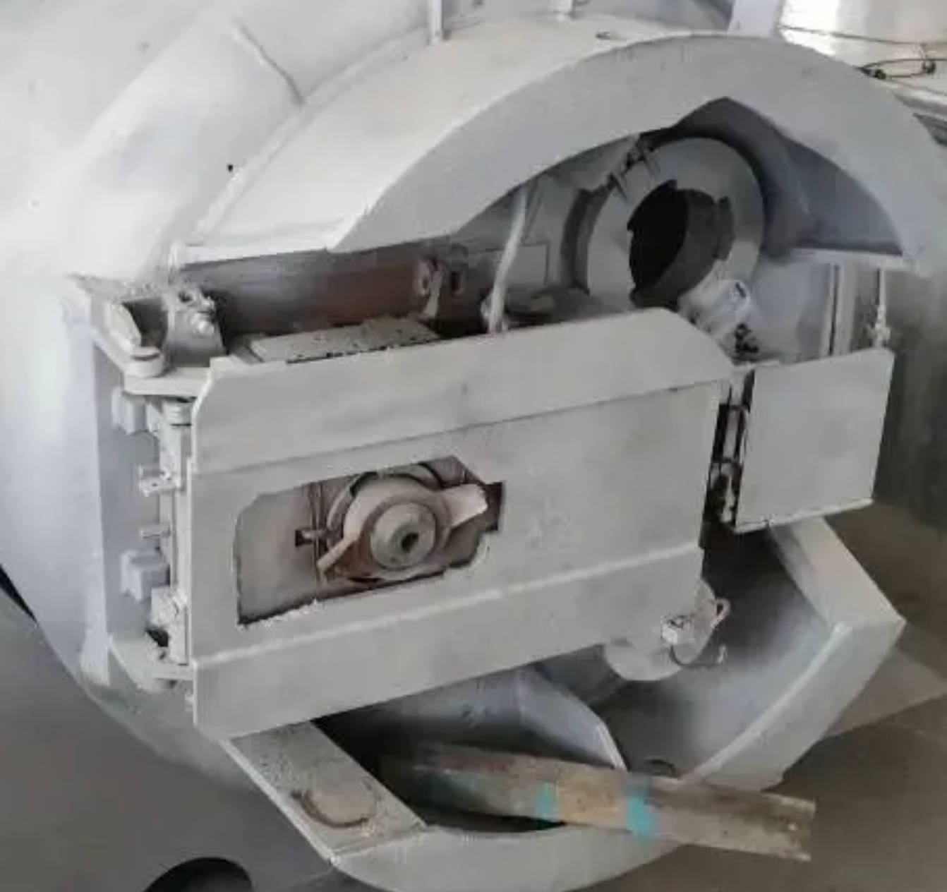
Bottom-opening configuration
As shown in Figure 3-2
Here, the hydraulic cylinder is mounted below the ladle outlet, usually with a long connecting rod so that the cylinder stays farther from the nozzle.
Disadvantage: during hot repair, the cylinder is prone to splashing from molten steel and slag; cylinder insertion and removal are less convenient.
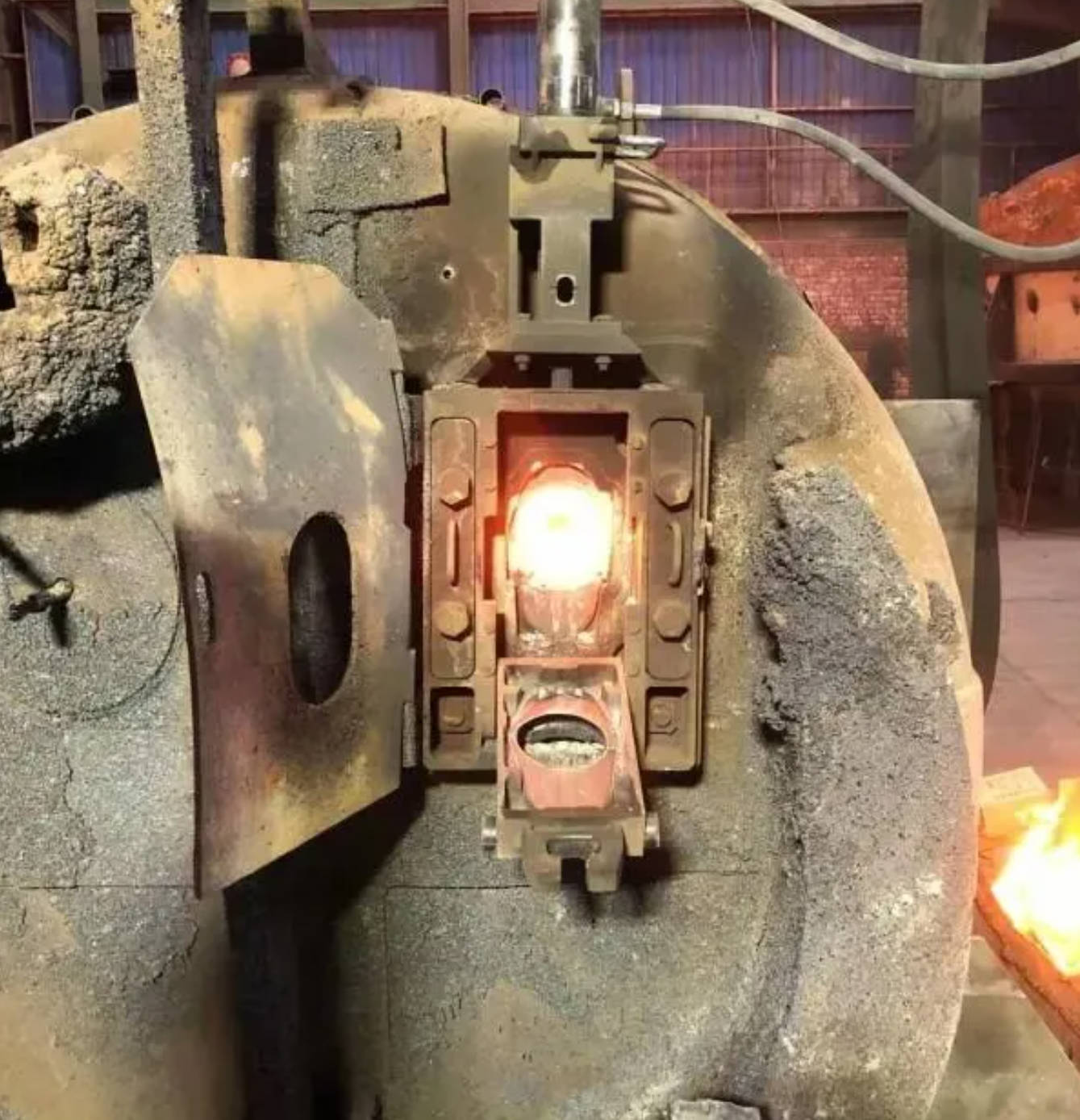
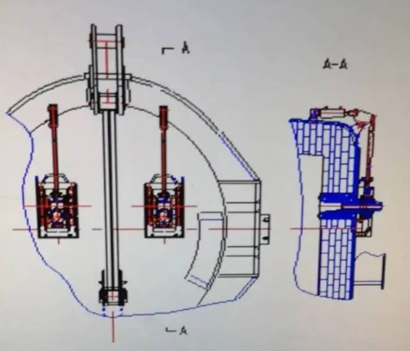
Side-opening configuration
As shown in Figure 3-3
For large-tonnage ladles, the slide gate assembly is relatively heavy. If the slide plate must be flipped upward or downward, workers face considerable labor intensity. To reduce this burden, many plants adopt a side-opening mechanism, whereby the slide block opens horizontally for slide plate replacement.
This layout is widely used in foreign designs.
Based on the direction of slide block opening:
Top or bottom-opening mechanisms are generally referred to as “A-type” mechanisms, as in Figure 3-4.
Left or right-opening mechanisms are generally referred to as “B-type” mechanisms, as in Figure 3-5.
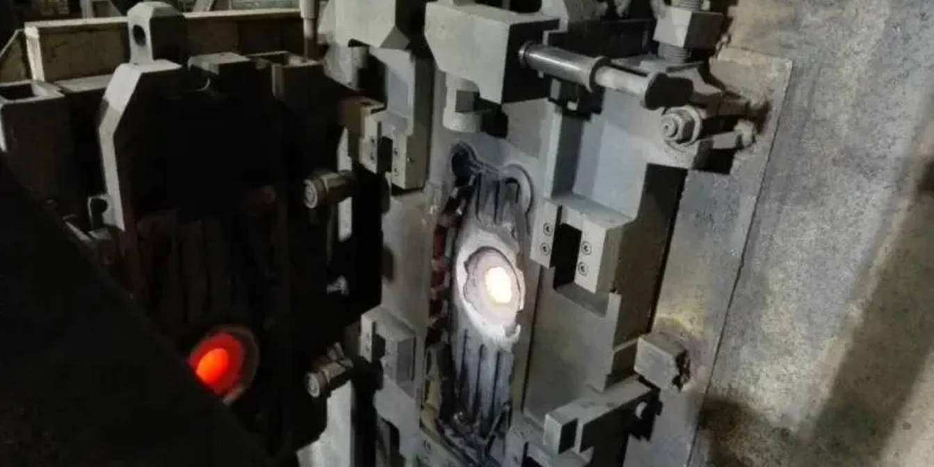
B-type mechanisms are more common on large slide plates and large-capacity ladles.
1.2 Layouts According to Different Drive Methods
Slide gate mechanisms on ladles can be classified into two drive configurations:
Direct-drive type (straight-push type)
Side-drive type
1.2.1 Direct-drive Layout
In a direct-drive slide gate system, the hydraulic cylinder support is directly fixed to the base of the slide gate mechanism, as shown earlier in Figure 3-4. During operation, no lateral force is transmitted to the mechanism base.
There are several possible installation orientations of the direct-drive mechanism at the ladle bottom, illustrated in the four variations (a, b, c, d) in Figure 3-6.
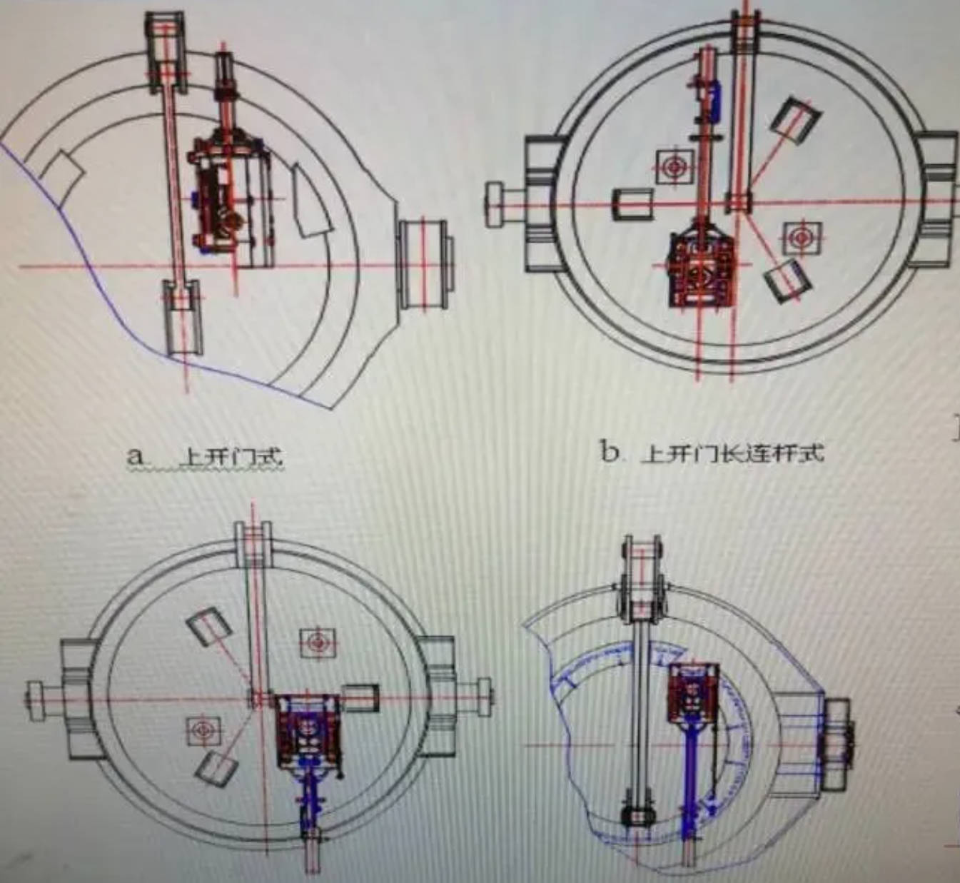
Advantages of the top-opening configuration:
During hot repair, molten steel and slag flowing from the ladle eye do not splash onto the hydraulic cylinder.
Advantages of the long-connecting-rod configuration:
On the continuous casting platform, the cylinder can remain farther away from radiant heat coming from the molten steel stream.
1.2.2 Side-drive Layout
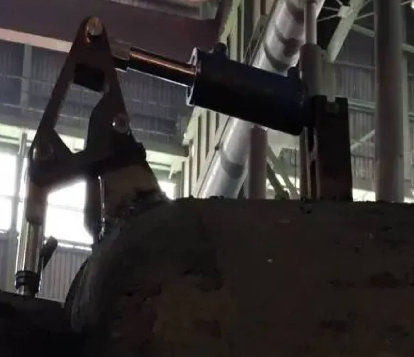
In a side-drive layout, the hydraulic cylinder is mounted on the ladle sidewall. Through a combination of lever arms, triangular brackets, and long connecting rods, the mechanism drives the slide plate to open or close the nozzle, as shown in Figure 3-7.
The arrangement of a side-drive system on a ladle is illustrated in Figure 3-8 (using either a single or double set of mechanisms).
Advantages of the side-drive layout:
When the ladle is opened for casting, the hydraulic cylinder is positioned on the side and is shielded from the direct radiant heat of the molten steel.
Important requirement:
The two supporting structures—the triangular support bracket and the hydraulic-cylinder support—must be precisely aligned and welded using dedicated installation fixtures. Incorrect positioning will lead to binding or misalignment during operation.
In older steel plants undergoing equipment upgrades, where the continuous casting turret lacks internal hydraulic piping and therefore cannot support pre-installation of the hydraulic cylinder at the ladle-receiving position, the side-drive configuration becomes a suitable alternative.
With this arrangement, the hydraulic cylinder can be inserted or removed directly at the casting station on the continuous casting platform. The hydraulic piping layout is simple, as shown in Figure 3-9.