1. Introduction
In modern steelmaking, precise control of molten steel flow is critical for achieving stable casting operations, high steel cleanliness, and long refractory service life. One of the most essential yet often underestimated components in the steel teeming system is the ladle nozzle. Located at the bottom of the steel ladle, the ladle nozzle serves as the primary outlet through which molten steel is transferred from the ladle to downstream vessels such as the tundish or directly to molds in special processes.
The ladle nozzle operates under extreme thermal, mechanical, and chemical conditions. It must withstand temperatures exceeding 1550 °C, aggressive molten steel and slag attack, and repeated thermal cycling, while still providing accurate and stable flow control. Understanding how the ladle nozzle works is therefore essential for metallurgists, refractory engineers, casting operators, and process designers.
This article provides a comprehensive explanation of the working principle of the ladle nozzle, including its structure, materials, flow control mechanisms, interaction with slide gate or stopper systems, and key operational challenges.

2. Role of the Ladle Nozzle in the Steelmaking Process
The ladle nozzle is a functional refractory component installed at the ladle bottom. Its main roles include:
- Allowing controlled discharge of molten steel
- Maintaining a sealed steel flow path
- Preventing air aspiration and secondary oxidation
- Providing mechanical support for flow control systems
- Withstanding erosion, corrosion, and thermal shock
The ladle nozzle does not work alone. It operates as part of a system, typically including:
- Slide gate plates or stopper rods
- Seating blocks or well blocks
- Ladle shrouds or collector nozzles
- Argon purging channels (in some designs)
The combined performance of these components determines the stability and cleanliness of the casting operation.
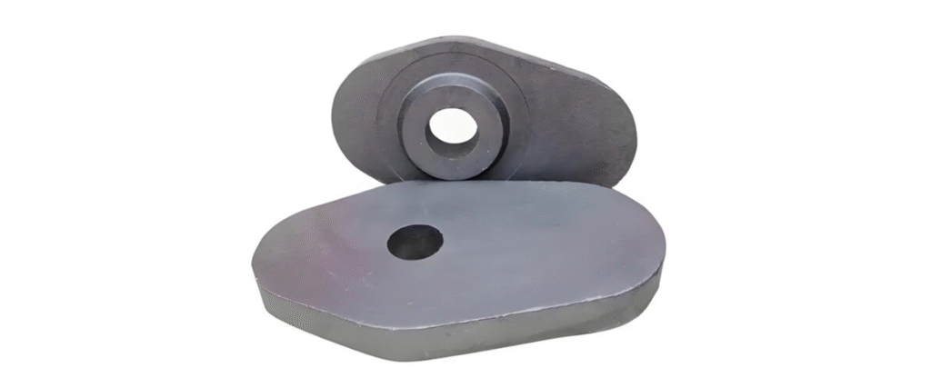
3. Structural Design of a Ladle Nozzle
3.1 Basic Geometry
A ladle nozzle is generally a cylindrical or slightly conical refractory block with a central bore. It is installed vertically at the bottom of the ladle shell. The geometry is carefully designed to:
- Control steel flow velocity
- Minimize turbulence
- Reduce erosion at the bore
- Ensure tight contact with downstream refractories
The internal bore diameter typically ranges from 40 mm to 100 mm, depending on ladle capacity, casting speed, and steel grade.
3.2 Multi-layer Structure
Modern ladle nozzles often adopt a composite or layered structure, which may include:
- Wear-resistant inner liner (e.g., zirconia or alumina-carbon)
- Structural outer body (e.g., high-alumina or alumina-magnesia)
- Thermal insulation layer (optional)
- Gas channels for argon purging (in porous designs)
This layered design balances mechanical strength, corrosion resistance, and thermal stability.
4. Materials Used in Ladle Nozzles
The working principle of a ladle nozzle is closely linked to its material selection.
4.1 Alumina-Based Nozzles
High-alumina materials (Al₂O₃ > 90%) are commonly used due to their:
- High refractoriness
- Good corrosion resistance
- Stable thermal behavior
However, pure alumina nozzles may suffer from steel penetration and bore clogging when casting aluminum-killed steels.
4.2 Alumina-Carbon Nozzles
Alumina-carbon (Al₂O₃–C) ladle nozzles are widely used because carbon:
- Improves thermal shock resistance
- Reduces wettability by molten steel
- Helps prevent clogging
Antioxidants such as Al, Si, or B₄C are often added to prevent carbon oxidation.
4.3 Zirconia Inserts
Some ladle nozzles include ZrO₂ inserts in the bore area. Zirconia offers:
- Exceptional corrosion resistance
- Extremely low wettability
- Long service life
These inserts are especially effective for high-cleanliness steels and long casting sequences.
5. How the Ladle Nozzle Works: Operating Principle

5.1 Steel Flow Initiation
When molten steel is ready for casting, the ladle nozzle remains closed by a slide gate plate or stopper rod. Once casting begins:
- The slide gate opens or the stopper rod lifts.
- Molten steel flows by gravity into the nozzle bore.
- Steel accelerates through the nozzle due to hydrostatic pressure.
The flow rate is primarily controlled by:
- Bore diameter
- Steel head pressure
- Opening degree of the slide gate or stopper
5.2 Flow Control and Stability
The ladle nozzle works as a flow conditioning element. Its smooth internal surface and optimized bore length help:
- Reduce turbulence
- Prevent vortex formation
- Maintain stable flow into the ladle shroud or tundish
Stable flow is critical to avoid:
- Slag entrainment
- Air aspiration
- Unstable casting speeds
5.3 Interaction with Slide Gate Systems
In slide gate systems, the ladle nozzle is tightly coupled with:
- Upper nozzle
- Middle plate
- Lower plate
The ladle nozzle must maintain excellent dimensional accuracy to ensure sealing between these components. Any mismatch can cause:
- Steel leakage
- Air ingress
- Accelerated plate wear
5.4 Sealing and Anti-Oxidation Function
The ladle nozzle provides a sealed flow path from the ladle interior to the ladle shroud. Proper operation prevents:
- Atmospheric oxygen from entering the steel stream
- Nitrogen pickup
- Inclusion formation
In advanced systems, argon gas may be injected through porous zones in the nozzle to further protect the steel.
6. Argon Purging and Clogging Prevention
6.1 Clogging Mechanism
One of the major operational problems in ladle nozzles is bore clogging, mainly caused by:
- Al₂O₃ inclusion deposition
- Calcium aluminate buildup
- Reoxidation products
Clogging restricts flow and destabilizes casting.
6.2 Argon Injection Working Principle
Some ladle nozzles are designed with argon channels. During operation:
- Low-pressure argon flows through micro-pores or slots
- Argon forms a thin gas film along the bore
- Inclusions are prevented from adhering to the wall
This mechanism significantly improves nozzle performance in aluminum-killed steel casting.
7. Thermal and Mechanical Behavior During Operation
7.1 Thermal Shock Resistance
The ladle nozzle experiences:
- Rapid heating during tapping
- Cooling during ladle emptying
- Reheating in subsequent heats
Carbon-containing and composite materials help absorb thermal stress and prevent cracking.
7.2 Mechanical Load and Erosion
The nozzle must withstand:
- Steel static pressure
- Abrasive flow
- Vibration from slide gate movement
High-density materials and optimized microstructures are essential for durability.
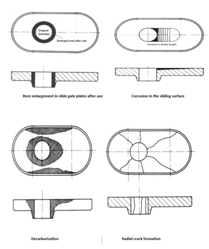
8. Failure Modes of Ladle Nozzles
Understanding how the ladle nozzle works also requires a clear understanding of how and why it fails in service. Ladle nozzle failure not only shortens refractory life but can directly cause casting interruptions, steel quality defects, and safety risks.
8.1 Erosion and Washout
Erosion is one of the most common failure mechanisms. During casting, molten steel flows through the nozzle bore at high velocity, carrying inclusions and slag droplets. Over time, this leads to:
- Enlargement of the nozzle bore
- Loss of dimensional accuracy
- Increased flow rate beyond target values
- Turbulence at the tundish entry
Erosion is most severe at:
- The inlet edge of the nozzle
- The outlet transition zone
- Areas with microstructural inhomogeneity
Materials such as zirconia inserts or ultra-high-density alumina-carbon are used to mitigate this phenomenon.
8.2 Chemical Corrosion
Chemical corrosion occurs due to reactions between molten steel, slag, and the refractory material. Typical reactions include:
- Reduction of SiO₂ by dissolved aluminum
- Penetration of FeO-rich slag into pores
- Dissolution of MgO or Al₂O₃ into aggressive slags
Corrosion leads to:
- Structural weakening
- Increased porosity
- Accelerated erosion
Optimized chemical composition and low open porosity are critical to corrosion resistance.
8.3 Thermal Cracking and Spalling
Thermal shock is unavoidable during ladle operation. Cracks may develop due to:
- Rapid temperature gradients
- Uneven heating of composite layers
- Differential thermal expansion between insert and matrix
If cracks propagate to the bore surface, steel penetration may occur, leading to catastrophic failure. Carbon-containing materials and engineered microstructures are key to absorbing thermal stress.
8.4 Bore Clogging
Clogging does not directly destroy the nozzle but disrupts its function. It manifests as:
- Reduced steel flow rate
- Increased slide gate opening demand
- Sudden flow fluctuations
- Casting interruptions
Clogging is particularly severe when casting:
- Aluminum-killed steels
- Ultra-low carbon steels
- High cleanliness grades
Anti-clogging nozzle designs and argon purging systems are therefore integral to modern ladle nozzle operation.
9. Installation and Working Integration in the Ladle
9.1 Nozzle Seating and Alignment
The ladle nozzle must be precisely installed into the ladle bottom refractory system, typically in combination with:
- Well block
- Seating block
- Slide gate housing
Correct alignment ensures:
- Uniform load distribution
- Proper sealing with slide gate plates
- Stable steel flow
Poor installation can cause misalignment, resulting in leakage or premature wear.
9.2 Interaction with Ladle Shroud
The ladle nozzle outlet is connected to a ladle shroud, which transfers steel to the tundish under protected conditions. The nozzle must provide:
- A smooth transition
- Tight mechanical fit
- Minimal air gap
This interface is critical for preventing secondary oxidation and nitrogen pickup.
10. Ladle Nozzle Working Conditions Across Steel Grades
The working behavior of a ladle nozzle varies depending on steel chemistry and casting practice.
10.1 Carbon and Low-Alloy Steels
For conventional grades:
- Flow is relatively stable
- Corrosion is moderate
- Alumina-carbon nozzles perform well
Service life is typically limited by erosion rather than clogging.
10.2 Aluminum-Killed Steels
These steels present the greatest challenge:
- Strong tendency for Al₂O₃ formation
- High clogging risk
- Sensitivity to oxygen ingress
Here, the ladle nozzle must combine:
- Low wettability
- Argon purging capability
- Anti-oxidation additives
10.3 Clean and Ultra-Clean Steels
For automotive and bearing steels:
- Inclusion control is critical
- Flow stability is essential
- Any nozzle degradation impacts product quality
Zirconia-based or engineered composite nozzles are commonly used.
11. Advances in Ladle Nozzle Technology
Modern steel plants demand longer sequence casting, higher productivity, and stricter quality control. As a result, ladle nozzle technology has evolved significantly.
11.1 Composite and Functionally Graded Nozzles
Instead of uniform materials, advanced nozzles feature:
- High-purity zirconia at the bore
- Alumina-carbon transition layers
- Structural outer shells
This allows each zone to perform its specific function optimally.
11.2 Anti-Clogging and Porous Nozzles
Porous plug technology has been adapted to ladle nozzles, enabling:
- Uniform argon distribution
- Reduced inclusion adhesion
- More stable casting rates
Careful control of pore size and gas flow is essential to avoid steel turbulence.
11.3 Digital Monitoring and Predictive Control
Some steelmakers integrate:
- Flow rate monitoring
- Pressure feedback systems
- Casting data analytics
These systems indirectly assess nozzle condition and help operators react before failure occurs.
12. Operational Best Practices for Ladle Nozzle Performance
Even the best nozzle design will fail prematurely without proper operation.
12.1 Preheating
Proper preheating:
- Reduces thermal shock
- Prevents moisture-related spalling
- Ensures smooth startup
Temperature gradients must be controlled carefully.
12.2 Controlled Opening Practices
Abrupt opening of slide gates can cause:
- Steel jet impingement
- Accelerated erosion
- Bore damage
Gradual opening improves nozzle life and flow stability.
12.3 Argon Flow Optimization
Excessive argon can:
- Disturb steel flow
- Entrain slag
- Increase turbulence
Insufficient argon, on the other hand, reduces anti-clogging effectiveness. Optimization is essential.
13. Safety Considerations in Ladle Nozzle Operation
The ladle nozzle is a critical safety component. Failure can lead to:
- Molten steel leakage
- Burn-through of ladle shell
- Severe injury or equipment damage
Therefore:
- Quality control during manufacturing
- Inspection before installation
- Strict adherence to operating procedures
are non-negotiable.
14. Summary and Conclusions
The ladle nozzle is far more than a simple refractory hole at the bottom of a steel ladle. It is a highly engineered flow-control component that plays a decisive role in:
- Steel flow stability
- Inclusion control
- Casting safety
- Overall process efficiency
How the Ladle Nozzle Works — In Essence:
- Molten steel flows by gravity through a precisely engineered bore
- Flow is regulated by slide gate or stopper systems
- The nozzle conditions the flow, protects the steel from oxidation, and interfaces with downstream protection systems
- Advanced materials and designs ensure resistance to erosion, corrosion, thermal shock, and clogging
As steelmaking continues to evolve toward higher cleanliness, longer sequences, and tighter tolerances, the working principles, materials, and design of ladle nozzles will remain a key area of technical development and operational focus.