Abstract: monoblock stopper rods in tundishes are crucial functional components for continuous casting, playing roles such as flow control and post-pouring flow blocking during the continuous casting process. Problems with the stopper rods during use can disrupt the continuous casting production rhythm and lead to serious safety accidents or significant economic losses. This paper summarizes the problems encountered in the application of monoblock stopper rods in tundishes in dozens of steel enterprises both domestically and internationally. Through classification and analysis, the problems are addressed from three aspects: the stopper rod head, the rod body, and the connecting parts. Effective countermeasures for various problems are proposed, hoping to contribute to the proper use of integral stopper rods in steel enterprises.
Keywords: stopper rod; erosion; scouring; fracture
The monoblock stopper rod of the tundish is one of the most important control components in the continuous casting process. It is installed in the tundish and works in conjunction with the internal submerged entry nozzle or the tundish top nozzle to control the flow rate of molten steel from the tundish to the crystallizer in the continuous casting process, so as to ensure the stability of the liquid level of molten steel in the crystallizer and the stability of the continuous casting process. Due to the irreplaceability of the stopper rod during use, once the stopper rod has a problem, it will lead to uncontrolled steel loss or even stop casting, causing the continuous casting to be interrupted, resulting in serious safety accidents or huge economic losses. In this paper, the problems encountered in the application of integral stopper rods of tundish in dozens of steel companies at home and abroad are summarized, and various problems are analyzed in detail. Effective countermeasures for various problems are proposed, hoping to help the normal use of integral stopper rods of tundish in steel companies.
1. Main problems encountered in the use of monoblock stopper rods in intermediate tundish
1.1 Introduction to the tundish Stopper
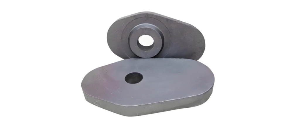
The tundish stopper rod, as shown in Figure 1, generally includes several parts such as the rod head, rod body, slag line, and connectors.

1.2 Problems encountered during the use of the stopper head
The stopper head is the key component of the stopper rod. It works in conjunction with the inlet to control flow, therefore requiring excellent erosion resistance. The head is typically made of materials such as aluminum-carbon, magnesium-carbon, spinel-carbon, or zirconium-carbon, with a carbon content generally much lower than that of the rod body.
The main problems that occur during the use of the head are severe head erosion and head breakage due to sticking.
1.2.1 Severe erosion of the stopper head
When the stopper rod head is severely eroded, the rounded shape of the rod head can be seen to have been eroded into a concave shape. This change in the rod head shape leads to a poor fit with the inlet spout, resulting in unstable flow control or even loss of flow control function. In one instance, the stopper rod height was reduced from 1250mm to 1225mm, and 25mm of the rod head was eroded away. This reduction in height causes the stopper rod to be unable to effectively control flow and to close properly when water is stopped.
1.2.2 the stopper rod head drop
The stopper rod head separated from the rod body, reducing the stopper rod height from 1725mm to 1600mm, and the rod head dropped by 125mm. As a result, the stopper rod could not control the flow properly, causing the continuous casting to stop.
1.3 Problems encountered during the use of the stopper rod
The stopper rod body is composed of the rod body material and the slag line material. The stopper rod body needs appropriate strength to prevent breakage during use, and is generally made of aluminum-carbon material. The stopper rod slag line needs good resistance to slag erosion, and is generally made of spinel-carbon, zircon-carbon, etc. The main problem with the rod body during use is transverse fracture, which is divided into transverse fracture of the rod body and transverse fracture of the slag line.
When a transverse fracture occurs in the body of an integral stopper rod during the steel casting process, provided the wall thickness of the stopper rod is sufficient, it generally occurs in the middle of the stopper rod, with a clean, knife-edge-shaped fracture.
1.4 Problems encountered during the use of stopper rod connectors
Stopper rod connections generally employ several methods, including metal wire plugs, carbon or ceramic wire plugs, and pin holes. Among these, metal wire plugs are the most widely used, with M39 metal wire plugs being the most common. Stopper rod connectors play a crucial role in continuous casting; loose connections or detachment can lead to casting stoppage. Common problems with stopper rod connectors include connector melting and cracking at the stopper rod tail.
2. Analysis of major problems encountered during use and improvement measures
2.1 Analysis of problems and improvement measures in the use of the rod tip
2.1.1 Analysis of the causes of severe rod head erosion and improvement measures
The compatibility of the stopper rod material with the continuous casting process is a crucial factor affecting rod erosion. Generally, the rod material should be selected based on the reaction of the cast steel and the refractory material. Rod erosion mainly involves three aspects: physical erosion, carbon oxidation, and oxide reactions. At higher vacuum levels, MgO reacts with C, accelerating rod erosion; high Ca content in the molten steel reacts with Al₂O₃, accelerating rod erosion; high oxygen content in the molten steel accelerates C oxidation, also accelerating rod erosion. Appropriate rod materials should be selected for different steel grades and operating conditions. Al₂O₃-C rods are more suitable for Al-killed steel than MgO-C rods, while the latter is very suitable for calcium-treated steel. The thin slag film containing CaO-Al₂O₃ compounds and MA and M₂S formed on the rod surface during casting effectively protects the rod from molten steel erosion (3-4). ZrO2-C rods are well adapted to the complex continuous casting environment of molten steel, mainly due to the corrosion resistance of ZrO2.
Excessive baking time is also a factor contributing to abnormal erosion of the stopper tip. Generally, stopper tip baking time is around 2 hours; baking for more than 4 hours will damage the anti-oxidation glaze layer, causing oxidation of the stopper tip from the surface inwards. Furthermore, the depth of oxidation increases with prolonged baking time. Once the tip material is oxidized, the carbon bonds are broken, leading to oxidation at high temperatures.It was rapidly damaged by the molten steel.
2.1.2 Analysis of the causes of rod tip deflection and improvement measures
There are many reasons why the head of the integral plug rod may turn off, generally due to thermal stress and mechanical stress.
Stopper rod deflection due to thermal stress is a common problem. Stopper rods typically undergo about 2 hours of baking before use, and the final baking temperature is crucial, generally reaching 1100℃. If the baking temperature is insufficient, the stopper rod is suddenly heated upon contact with the molten steel during casting. Due to the difference in thermal expansion coefficients between the rod head and body, thermal stress is generated inside the stopper rod, causing it to deflect due to stress concentration. The key to solving this problem is to strictly adhere to the stopper rod baking procedure.
In addition, some steel mills require the entire stopper rod to be shut down for baking, which causes the stopper rod to become stuck. Ineffective baking of the stopper tip can cause thermal stress concentration inside the stopper rod during the initial casting process, leading to it turning over. Figure 2 shows the digital model state when the stopper rod is closed during baking, indicating that the baking temperature of the stopper rod tip is relatively low.

There are many reasons why stopper rods may break due to mechanical stress. These include: the stopper rod head being misaligned with the center of the inlet during installation; using the stopper rod to strike the inlet when it is blocked; and excessive force being applied when changing a quick-change submersible inlet.
2.2 Analysis of problems and improvement measures in the use of the rod body
Transverse fracture of stopper rods is a common occurrence during continuous casting, with a high proportion of fractures caused by thermal stress, mechanical stress, and chemical corrosion.
The main causes of stopper rod fracture are thermal stress and mechanical stress. The primary factors affecting thermal stress are the baking time and temperature of the stopper rod. Mechanical stress fracture has many causes, such as misalignment between the stopper rod and the nozzle, excessive operating force, and crusting in the tundish preventing the stopper rod from rising or falling. These problems can be addressed by strictly implementing the baking procedure, training key stopper rod operators, and improving the continuous casting process.
The main causes of abnormal erosion in the slag line area of the stopper rod are unsuitable material selection and incorrect operation. Firstly, the material selection for the stopper rod slag line must be suitable for the continuous casting process requirements. It is essential to select a suitable slag line material based on the composition of the continuous casting slag and the tundish covering agent. For example, for steel grades with high MnO content, materials containing SiO2, SiC, and elemental Si powder should be avoided to prevent the formation of a low-melting-point eutectic phase of silicon, manganese, and oxygen, which would exacerbate erosion.
Slag discharge from the ladle is also a common cause of abnormal erosion of the stopper rod. Due to the failure of the automatic slag discharge detection system in the ladle during continuous casting or improper control of slag discharge from the ladle, a large amount of slag flows from the ladle into the tundish. At the same time, due to the poor slag blocking effect of the slag baffle or the failure to remove slag in time, slag accumulates around the stopper rod, causing abnormal erosion of the slag line on the stopper rod.
Adding mold flux to the tundish is also one of the reasons for abnormal erosion of the stopper rod slag line. During continuous casting, low tundish temperature and other factors can cause a crust to form on the tundish surface. In such cases, operators sometimes choose a crystallizer protective slag with a lower melting temperature to avoid crust formation.
The strong corrosiveness of the mold flux caused abnormal erosion of the stopper rod flux line.
2.3 Analysis of problems and improvement measures in the use of connectors
Problems at the stopper rod connector include cross-section breakage at the end of the stopper rod and melting of the lead screw; both of these issues occur frequently.
The main cause of transverse breakage at the plug of the stopper rod is installation problems. Excessive tightening force on the screw during installation, or impacts during adjustment, can all cause transverse breakage at the tail of the stopper rod. The metal plug inside the tail of the stopper rod is pre-embedded during the rod forming process, making the plug area a relatively weak area of the rod. During installation, it is crucial to maintain moderate force and to thoroughly inspect the tail of the stopper rod after installation; any cracks found should result in immediate removal from the production line.
The root cause of the stopper rod connector melting is a problem with the stopper rod design. If the stopper rod is designed to be too short, its tail cannot protrude from the tundish cover. During high-temperature baking or use, the temperature at the connector becomes too high, causing the lead screw to melt. The fundamental solution to this problem is to lengthen the stopper rod so that the connector protrudes from the tundish cover. Lengthening the stopper rod requires changing the stopper rod mechanism. Some steel mills, limited by the fixed height of the tundish stopper rod mechanism, can simply make the stopper rod crossarm stepped, as shown in Figure 3.
In addition, applying fire mortar between the stopper rod and the connector, and using asbestos gaskets instead of graphite gaskets between the rod and the connector are relatively convenient temporary measures. Applying fire putty between the rod and the connector can, to some extent, prevent heat transfer and reduce the risk of the connector melting; using asbestos gaskets instead of easily combustible and exothermic graphite gaskets can also reduce the risk of the connector melting; however, these two measures cannot fundamentally solve the problem.

3.Summary
Problems encountered during the application of integral stopper rods in tundishes were summarized, classified, and analyzed, and some effective and feasible measures were proposed. After long-term use and monitoring, significant results have been achieved in numerous steel mills both domestically and internationally, greatly reducing problems with the rod head, rod body, and connectors during use. This has effectively reduced casting stoppages caused by stopper rod issues, thereby significantly reducing the economic losses of steel mills.